ZXSC300
ISSUE 4 - SEPTEMBER 2007
8
APPLICATIONS INFORMATION
The following section is a design guide for optimum
converter performance.
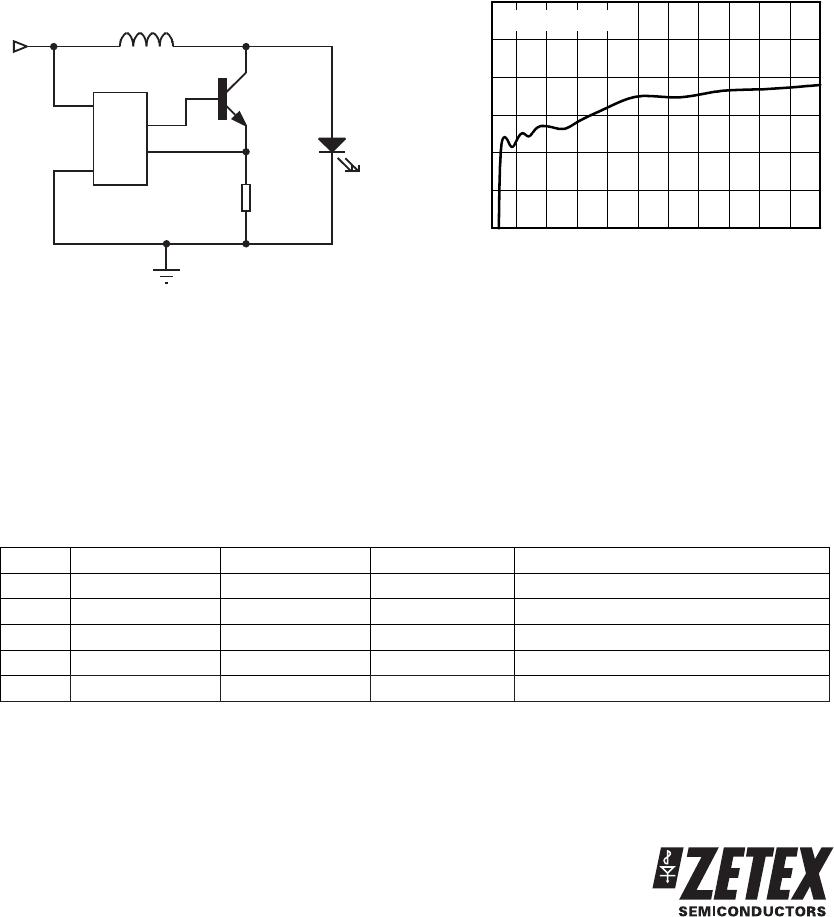
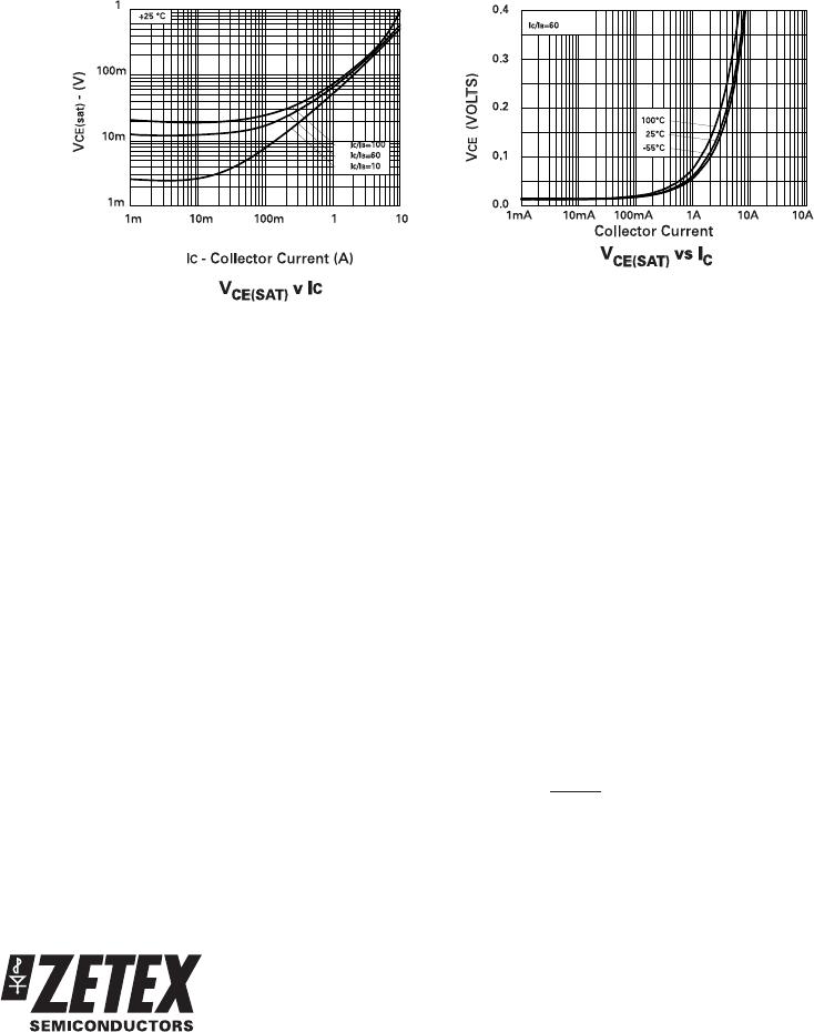
Switching transistor selection
The choice of switching transistor has a major impact
on the converter efficiency. For optimum
performance, a bipolar transistor with low V
CE(SAT)
and
high gain is required.
The Zetex FMMT617 is an ideal choice of transistor,
having a low saturation voltage. A data sheet for the
FMMT617 is available on Zetex web site or through
your local Zetex sales office. Outline information is
included in the characteristics section of this data
sheet.
Schottky diode selection
For the maximum efficiency a Schottky rectifier diode
is required not a normal silicon diode. As with the
switching transistor the Schottky rectifier diode has a
major impact on the converter efficiency. A Schottky
diode with a low forward voltage and fast recovery
time should be used for this application.
The diode should be selected so that the maximum
forward current is greater or equal to the maximum
peak current in the inductor, and the maximum reverse
voltage is greater or equal to the output voltage.
The Zetex ZHCS1000 meets these needs. Datasheets
for the ZHCS Series are available on Zetex web site or
through your local Zetex sales office. Outline
information is included in the characteristics section of
this data sheet.
For the maximum brightness solution a pulsed current
is supplied to the LED therefore a Schottky rectifier
diode is not required.
Inductor selection
The inductor value must be chosen to satisfy
performance, cost and size requirements of the overall
solution. For the reference designs we recommend an
inductor value of 100uH with a core saturation current
rating greater than the converter peak current value
and low series resistance.
Inductor selection has a significant impact on the
converter performance. For applications where
efficiency is critical, an inductor with a series
resistance of 500mΩ or less should be used.
Peak current definition
The peak current rating is a design parameter whose
value is dependent upon the overall application. For
the high brightness reference designs, a peak current
of 190mA was chosen to ensure that the converter
could provide the required output power to the LED.
In general, the I
PK
value must be chosen to ensure that
the switching transistor, Q1, is in full saturation with
maximum output power conditions, assuming
worse-case input voltage and transistor gain under all
operating temperature extremes.
Once I
PK
is decided the value of R
SENSE
can be
determined by:
R
V
I
SENSE
ISENSE
PK
=
where V
ISENSE
=19mV