Revised: 06/27/18
Specifications are subject to change without notice.
©2018 Littelfuse, Inc
Thyristors
12 Amp High Junction Temperature SCRs
SJxx12xx Series
SJxx12xx series
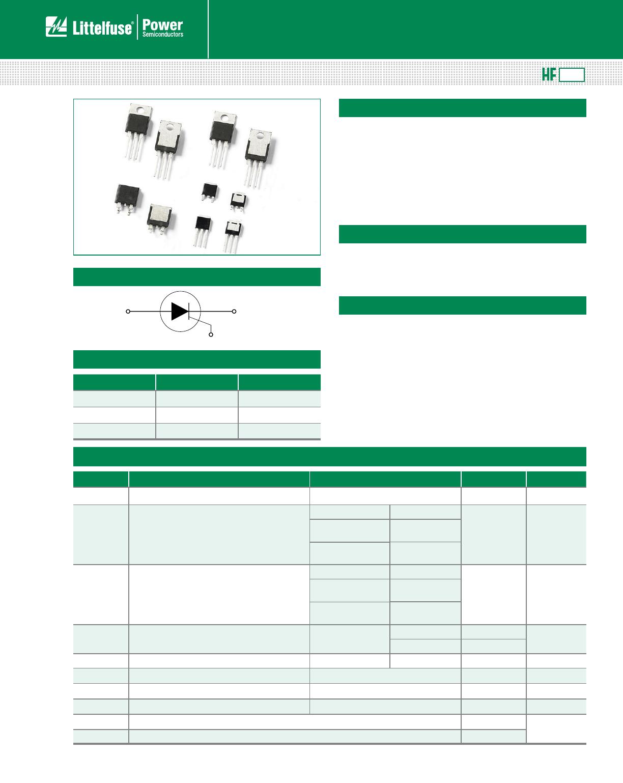
Description
This SJxx12xx high junction temperature SCR series is
ideal for uni-directional switch applications such as phase
control in heating, motor speed controls, converters/
rectifiers, inrush current control and capacitive discharge
ignitions.
These SCRs have a low gate current trigger level of 6mA,
10mA or 20mA maximum at approximately 1.5V.
Features & Benefits
• Halogen free and RoHS
compliant
• 150°C maximum junction
temperature
• Surge capability up to 120
A at 60 Hz half cycle
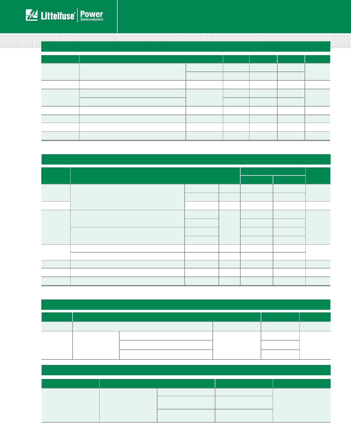
Main Features
Symbol Value Unit
I
T(RMS)
12 A
V
DRM
/V
RRM
400 or 600 V
I
GT
6 to 20 mA
Schematic Symbol
Applications
Typical applications include AC Generator (ACG) rectifiers,
battery voltage regulators and generic converters and
inrush current controller in various AC to DC applications.
Additional applications include controls for power tools,
home/brown good and white goods appliances.
Internally constructed isolated packages are offered for
ease of heat sinking with high isolation voltage.
RoHS
Absolute Maximum Ratings
Symbol Parameter Test Conditions Value Unit
V
DSM
/V
RSM
Peak non-repetitive blocking voltage Pw=100 μs V
DRM
/V
RRM
+100
V
I
T(RMS)
RMS on-state current
SJxx12Lx T
C
= 110°C
12 A
SJxx12Rx
SJxx12Nx
T
C
= 135°C
SJxx12Dx
SJxx12Vx
T
C
= 125°C
I
T(AV)
Average on-state current
SJxx12Lx T
C
= 110°C
7. 6 A
SJxx12Rx
SJxx12Ny
T
C
= 135°C
SJxx12Dx
SJxx12Vx
T
C
= 125°C
I
TSM
Peak non-repetitive surge current
(single half cycle, T
J
(initial) = 25°C)
f = 50Hz 100
A
f = 60Hz 120
I
2
t I
2
t Value for fusing t
p
= 8.3 ms 60 A
2
s
di/dt Critical rate of rise of on-state current
f = 60Hz; T
J
= 150°C
100 A/μs
I
GM
Peak gate current
T
J
= 150°C
2 A
P
G(AV)
Average gate power dissipation
T
J
= 150°C
0.5 W
T
stg
Storage temperature range -40 to 150
°C
T
J
Operating junction temperature range -40 to 150
Note: xx=voltage/10, x=sensitivity
SJxx12xx Series