Revised: 06/27/18
Specifications are subject to change without notice.
©2018 Littelfuse, Inc
Thyristors
12 Amp High Junction Temperature SCRs
SJxx12xx Series
Figure 7: Maximum Allowable Case Temperature
vs. Average On-State Current
80
90
100
110
120
130
CURRENT WAVEFORM: Sinusoidal
LOAD: Resistive or Inductive
CONDUCTION ANGLE: 180°
0 1 2 3 4 5 6 7 8
Average On-State Current [I
T(AVE)
] - Amps
Maximum Allowable Case
Te mperature (T
C
) - °C
140
150
SJxx12Rx
SJxx12Nx
SJxx12Lx
SJxx12Dx
SJxx12Vx
SJxx16Dx
SJxx16Vx
12 Amps High Junction Temperature SCRs
Figure 8: Peak Capacitor Discharge Current
10
100
1000
0.050.520.55.0
Peak Discharge Current (I
TM
) - Amps
Pulse Current Duration (t
w
) - ms
I
TRM
t
W
SJxx12xx Series
Figure 9: Peak Capacitor Discharge Current Derating
1
10
100
1000
0001001011
Peak Surge (Non-repetitive)
On-state Current (I
TSM
) – Amps
Surge Current Duration - Full Cycles
Figure 10: Surge Peak On-State Current vs. Number of Cycles
SUPPLY FREQUENCY: 60 Hz Sinusoidal
LOAD: Resistive
RMS On-State Current: [I
T(RMS)
]: Maximum Rated
Value at Specified Case Temperature
Notes:
1. Gate control may be lost during and immediately
following surge current interval.
2. Overload may not be repeated until junction
temperature has returned to steady-state
rated value.
0.0
0.2
0.4
0.6
0.8
1.0
1.2
0255075100 12
51
50
Case Temperature (T
C
) - ºC
Normalized Peak Current
Revised: 06/27/18
Specifications are subject to change without notice.
©2018 Littelfuse, Inc
Thyristors
12 Amp High Junction Temperature SCRs
SJxx12xx Series
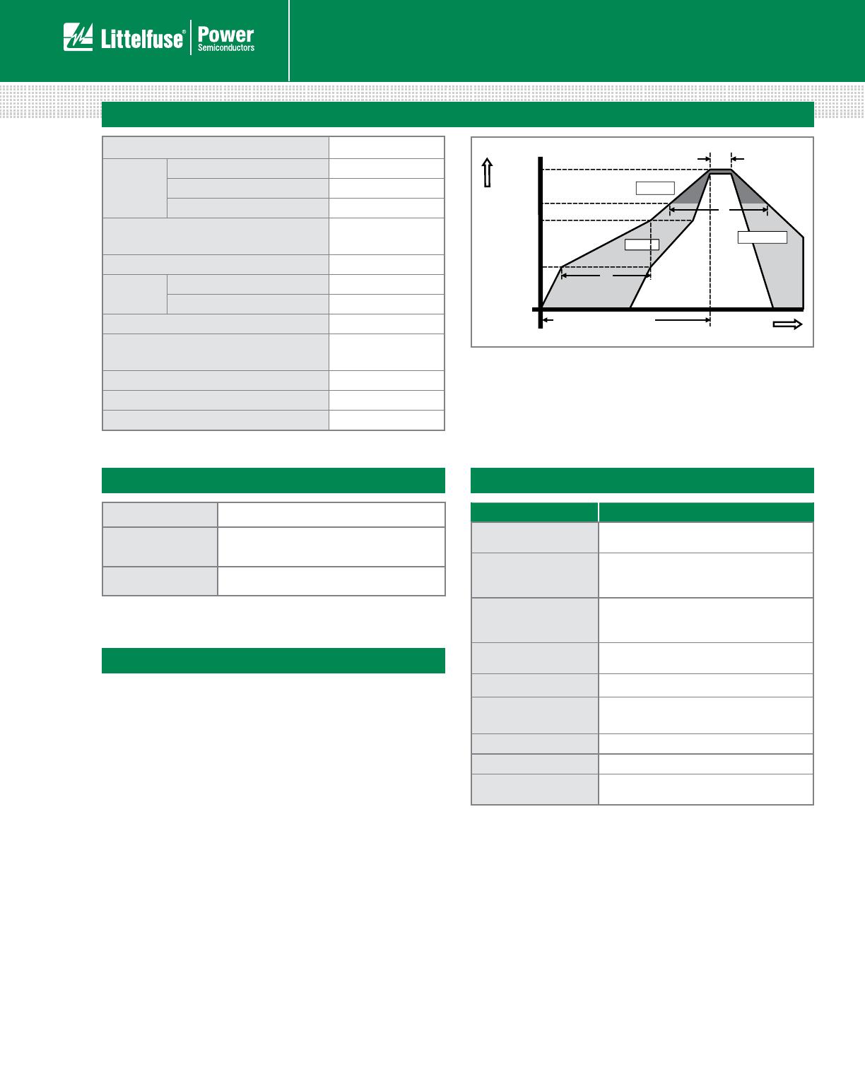
Soldering Parameters
Reflow Condition Pb – Free assembly
Pre Heat
- Temperature Min (T
s(min)
) 150°C
- Temperature Max (T
s(max)
) 200°C
- Time (min to max) (t
s
) 60 – 180 secs
Average ramp up rate (Liquidus Temp)
(T
L
) to peak
5°C/second max
T
S(max)
to T
L
- Ramp-up Rate 5°C/second max
Reflow
- Temperature (T
L
) (Liquidus) 217°C
- Time (t
L
) 60 – 150 seconds
Peak Temperature (T
P
) 260
+0/-5
°C
Time within 5°C of actual peak
Temperature (t
p
)
20 – 40 seconds
Ramp-down Rate 5°C/second max
Time 25°C to peak Temperature (T
P
) 8 minutes Max.
Do not exceed 280°C
Time
Temperature
T
P
T
L
T
S(max)
T
S(min)
25
t
P
t
L
t
S
time to peak temperature
Preheat
P
r
e
h
eat
Ramp-upRamp-up
Ramp-down
R
am
p
-
do
Physical Specifications Environmental Specifications
Test
Specifications and Conditions
AC Blocking
MIL-STD-750, M-1040, Cond A Applied
Peak AC voltage @ 150°C for 1008 hours
Temperature Cycling
MIL-STD-750, M-1051,
100 cycles; -55°C to +150°C;
15-min dwell-time
Temperature/
Humidity
EIA / JEDEC, JESD22-A101
1008 hours; 160V - DC: 85°C;
85% rel humidity
High Temp Storage
MIL-STD-750, M-1031,
1008 hours; 150°C
Low-Temp Storage 1008 hours; -40°C
Resistance to
Solder Heat
MIL-STD-750 Method 2031
Solderability ANSI/J-STD-002, category 3, Test A
Lead Bend MIL-STD-750, M-2036 Cond E
Moisture Sensitivity
Level
Level 1, JEDEC-J-STD-020D
Terminal Finish 100% Matte Tin-plated
Body Material
UL recognized compound meeting
flammability rating V-0.
Lead Material Copper Alloy
Design Considerations
Careful selection of the correct component for the
applications operating parameters and environment will
go a long way toward extending the operating life of the
Thyristor. Good design practice should limit the maximum
continuous current through the main terminals to 75% of
the component rating. Other ways to ensure long life for
a power discrete semiconductor are proper heat sinking
and selection of voltage ratings for worst case conditions.
Overheating, overvoltage (including dv/dt), and surge
currents are the main killers of semiconductors. Correct
mounting, soldering, and forming of the leads also help
protect against component damage.
12 Amps High Junction Temperature SCRs
SJxx12xx Series
Revised: 06/27/18
Specifications are subject to change without notice.
©2018 Littelfuse, Inc
Thyristors
12 Amp High Junction Temperature SCRs
SJxx12xx Series
Dimensions — TO-220AB (L-Package) — Isolated Mounting Tab
Dimension
Inches Millimeters
Min Max Min Max
A 0.380 0.420 9.65 10.67
B 0.105 0.115 2.67 2.92
C 0.230 0.250 5.84 6.35
D 0.590 0.620 14.99 15.75
E 0.142 0.147 3.61 3.73
F 0.110 0.130 2.79 3.30
G 0.540 0.575 13.72 14.61
H 0.025 0.035 0.64 0.89
J 0.195 0.205 4.95 5.21
K 0.095 0.105 2.41 2.67
L 0.060 0.075 1.52 1.91
M 0.085 0.095 2.16 2.41
N 0.018 0.024 0.46 0.61
O 0.178 0.188 4.52 4.78
P 0.045 0.060 1. 14 1.52
R 0.038 0.048 0.97 1.22
A
H
G
B
F
E
C
D
L
R
T
C
MEASURING POINT AREA (REF.) 0.17 IN
2
O
P
N
M
.320
8.13
.526
13.36
.276
7. 01
K
J
GATECATHODE
ANODE
Dimensions — TO-220AB (R-Package) — Non-Isolated Mounting Tab Common with Center Lead
Dimension
Inches Millimeters
Min Max Min Max
A 0.380 0.420 9.65 10.67
B 0.105 0.115 2.67 2.92
C 0.230 0.250 5.84 6.35
D 0.590 0.620 14.99 15.75
E 0.142 0.147 3.61 3.73
F 0.110 0.130 2.79 3.30
G 0.540 0.575 13.72 14.61
H 0.025 0.035 0.64 0.89
J 0.195 0.205 4.95 5.21
K 0.095 0.105 2.41 2.67
L 0.060 0.075 1.52 1.91
M 0.085 0.095 2.16 2.41
N 0.018 0.024 0.46 0.61
O 0.178 0.188 4.52 4.78
P 0.045 0.060 1. 14 1.52
R 0.038 0.048 0.97 1.22
K
J
A
H
G
B
F
E
C
D
L
R
T
C
MEASURING POINT
ANODE
O
P
N
M
.276
7. 01
.526
13.36
.320
8.13
AREA (REF.) 0.17 IN
2
NOTCH IN
GATE LEAD
TO ID.
NON-ISOLATED
TAB
GATECATHODE
ANODE
Note: Maximum torque to
be applied to mounting tab
is 8 in-lbs. (0.904 Nm).
12 Amps High Junction Temperature SCRs
SJxx12xx Series

SJ6012R1TP

Mfr. #:
Manufacturer:
Littelfuse
Description:
SCRs 12A High Temp Thyristor
Lifecycle:
New from this manufacturer.
Delivery:
DHL FedEx Ups TNT EMS
Payment:
T/T Paypal Visa MoneyGram Western Union