©2008 Integrated Device Technology, Inc.
1
OCTOBER 2008
DSC-4869/7
CE
0R
R/
W
R
CE
1R
BE
0R
BE
1R
BE
2R
BE
3R
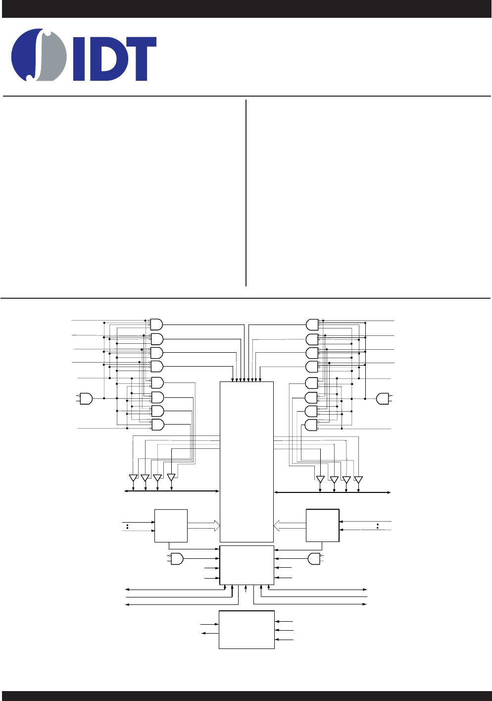
128/64/32K x 36
MEMORY
ARRAY
Address
Decoder
A
16R
(1)
A
0R
Address
Decoder
CE
0L
R/
W
L
CE
1L
BE
0L
BE
1L
BE
2L
BE
3L
Dout0-8_L
Dout9-17_L
Dout18-26_L
Dout27-35_L
Dout0-8_R
Dout9-17_R
Dout18-26_R
Dout27-35_R
B
E
0
L
B
E
1
L
B
E
2
L
B
E
3
L
B
E
3
R
B
E
2
R
B
E
1
R
B
E
0
R
I/O
0L-
I/O
35L
A
16 L
(1)
A
0L
I/O
0R -
I/O
35R
Di n_L
ADDR_L
Di n_R
ADDR_R
OE
R
OE
L
ARBITRATION
INTERRUPT
SEMAPHORE
LOGIC
SEM
L
INT
L
(3)
BUSY
L
(2,3)
M/S
R/W
L
OE
L
R/W
R
OE
R
CE
0L
CE
1L
CE
0R
CE
1R
BUSY
R
(2,3)
SEM
R
INT
R
(3)
TMS
TCK
TRST
TDI
TDO
JTAG
4869 drw 01
Functional Block Diagram
◆◆
◆◆
◆
Full on-chip hardware support of semaphore signaling
between ports
◆◆
◆◆
◆
Fully asynchronous operation from either port
◆
Separate byte controls for multiplexed bus and bus
matching compatibility
◆◆
◆◆
◆
Supports JTAG features compliant to IEEE 1149.1
◆◆
◆◆
◆
LVTTL-compatible, single 3.3V (±150mV) power supply for
core
◆◆
◆◆
◆
LVTTL-compatible, selectable 3.3V (±150mV)/2.5V (±100mV)
power supply for I/Os and control signals on each port
◆◆
◆◆
◆
Available in a 208-pin Plastic Quad Flatpack, 208-ball fine
pitch Ball Grid Array, and 256-ball Ball Grid Array
◆◆
◆◆
◆
Industrial temperature range (–40°C to +85°C) is available
for selected speeds
◆◆
◆◆
◆
Green parts available, see ordering information
Features
◆◆
◆◆
◆
True Dual-Port memory cells which allow simultaneous
access of the same memory location
◆◆
◆◆
◆
High-speed access
– Commercial: 10/12/15ns (max.)
– Industrial: 12/15ns (max.)
◆◆
◆◆
◆
Dual chip enables allow for depth expansion without
external logic
◆◆
◆◆
◆
IDT70V659/58/57 easily expands data bus width to 72 bits
or more using the Master/Slave select when cascading
more than one device
◆◆
◆◆
◆
M/S = VIH for BUSY output flag on Master,
M/S = VIL for BUSY input on Slave
◆◆
◆◆
◆
Busy and Interrupt Flags
◆◆
◆◆
◆
On-chip port arbitration logic
HIGH-SPEED 3.3V
128/64/32K x 36
ASYNCHRONOUS DUAL-PORT
STATIC RAM
IDT70V659/58/57S
1. A16 is a NC for IDT70V658. Also, Addresses A16 and A15 are NC's for IDT70V657.
2. BUSY is an input as a Slave (M/S=V
IL) and an output when it is a Master (M/S=VIH).
3. BUSY and INT are non-tri-state totem-pole outputs (push-pull).
NOTES: