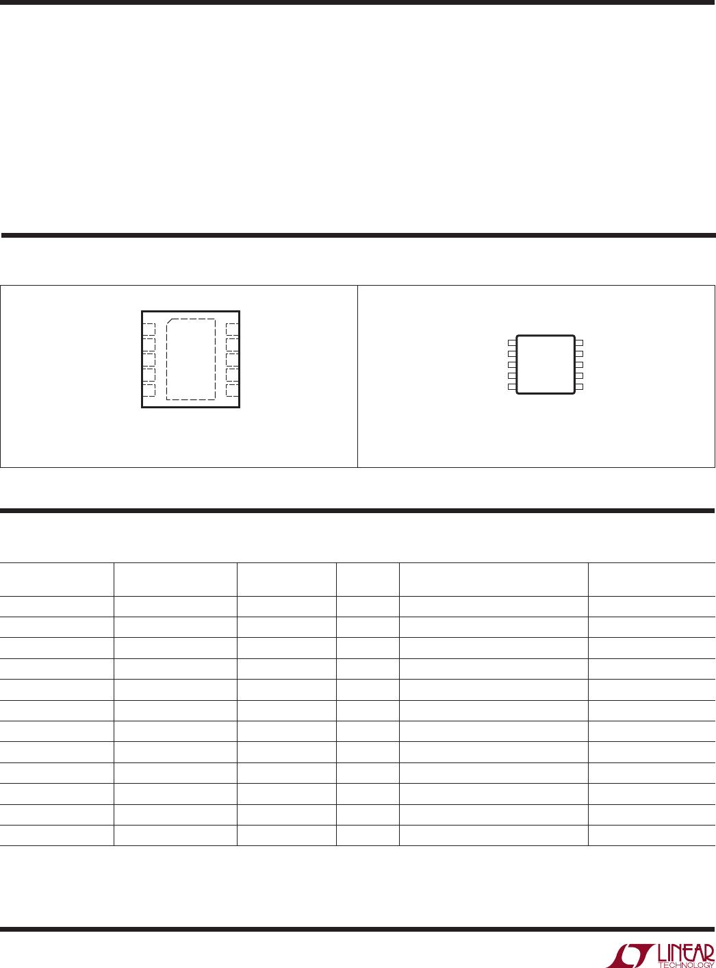
LT4275BIDD#PBF

LT4275
1
4275f
Typical applicaTion
FeaTures DescripTion
LTPoE
++
/PoE
+
/PoE
PD Controller
The LT
®
4275 is a pin-for-pin compatible family of IEEE
802.3 and LTPoE
++
powered device (PD) controllers.
The LT4275A employs a proprietary LTPoE
++
classification
scheme, delivering 38.7W, 52.7W, 70W or 90W of power
at the PD RJ45 connector. The LT4275A is fully compat-
ible with IEEE 802.3. The LT4275B is an IEEE 802.3at
compliant, Type 2 (PoE
+
) PD delivering up to 25.5W. The
LT4275C is an IEEE 802.3af compliant, Type 1 (PoE) PD
delivering up to 13W.
The LT4275 internal charge pump provides an N-channel
MOSFET solution, eliminating a larger and more costly
P-channel MOSFET. A low R
DS(ON)
MOSFET also maxi-
mizes power delivery and efficiency, reduces power and
heat dissipation, and eases thermal design. Startup inrush
current is adjustable with an external capacitor. The LT4275
also includes a power good output, on-board signature
resistor, undervoltage lockout, and thermal protection. The
LT4275A/LT4275B drives a single opto-coupler to indicate
the power level of the attached PSE. Pin-selectable sup-
port for non-standard low voltage operation is provided.
Auxiliary power override is supported with the AUX pin.
The LT4275A can be configured to support all possible
LTPoE
++
, 802.3at
and 802.3af power levels with external
component changes.
L, LT, LTC , LT M, Linear Technology and the Linear logo are registered trademarks and
LTPoE
++
and Hot Swap are trademarks of Linear Technology Corporation. All other trademarks
are the property of their respective owners.
LTPoE
++
90W Powered Device Interface
applicaTions
n
IEEE 802.3af/at and LTPoE
++
™ Powered Device
(PD) Controller
n
LTPoE
++
Supports Power Levels Up to 90W
n
LT4275A Supports All of the Following Standards:
n
LTPoE
++
38.7W, 52.7W, 70W and 90W
n
IEEE 802.3at 25.5W Compliant
n
IEEE 802.3af Up to 13W Compliant
n
LT4275B is IEEE 802.3at/af Compliant
n
LT4275C is IEEE 802.3af Compliant
n
100V Absolute Maximum Input Voltage
n
Wide Junction Temperature Range (–40°C to 125°C)
n
Overtemperature Protection
n
Integrated Signature Resistor
n
External Hot Swap™ N-Channel MOSFET for Lowest
Power Dissipation and Highest System Efficiency
n
Programmable Aux Power Support as Low as 9V
n
Optional Support of Non-Standard Low Voltage PoE
n
Available in 10-Lead MSOP and 3mm × 3mm DFN
Packages
n
High Power Wireless Data Systems
n
Outdoor Security Camera Equipment
n
Commercial and Public Information Displays
n
High Temperature Industrial Applications
LT4275 Family
MAX DELIVERED
POWER
LT4275 GRADE
A B C
LTPoE
++
90W
l
LTPoE
++
70W
l
LTPoE
++
52.7W
l
LTPoE
++
38.7W
l
25.5W
l l
13W
l l l
LT4275A
VPORT HSGATE
GND
4275 TA01a
IEEEUVLO
HSSRC
AUX
RCLASS
RCLASS
++
R
CLS++
PWRGD
T2P
R
CLS
C
PD
0.1µF
V
PORT
DATA
PAIR
SPARE
PAIR
RUN
47nF
3.3k
FDMC86102
V
IN
V
OUT
+
ISOLATED
POWER
SUPPLY
OPTO
PSE TYPE
(TO µP)
+
~
~
+
~
~
+
C
PORT
V
AUX
(9V TO 60V)
LT4275
2
4275f
absoluTe MaxiMuM raTings
VPORT, HSSRC Voltages ......................... 0.3V to 100V
HSGATE Current.................................................. ±20mA
IEEEUVLO, RCLASS,
RCLASS
++
Voltages ....... 0.3V to 8V (andVPORT)
AUX Current ........................................................ ±1.4mA
T2P, PWRGD Voltage ............................... 0.3V to 100V
T2P, PWRGD Current ...............................................5mA
(Notes 1, 3)
orDer inForMaTion
LEAD FREE FINISH TAPE AND REEL PART MARKING*
MAX PD
POWER PACKAGE DESCRIPTION TEMPERATURE RANGE
LT4275AIDD#PBF LT4275AIDD#TRPBF LGBS 90W
10-Lead (3mm × 3mm) Plastic DFN
–40°C to 85°C
LT4275AHDD#PBF LT4275AHDD#TRPBF LGBS 90W
10-Lead (3mm × 3mm) Plastic DFN
–40°C to 125°C
LT4275AIMS#PBF LT4275AIMS#TRPBF LTGBT 90W 10-Lead Plastic MSOP
–40°C to 85°C
LT4275AHMS#PBF LT4275AHMS#TRPBF LTGBT 90W 10-Lead Plastic MSOP –40°C to 125°C
LT4275BIDD#PBF LT4275BIDD#TRPBF LGBV 25.5W
10-Lead (3mm × 3mm) Plastic DFN
–40°C to 85°C
LT4275BHDD#PBF LT4275BHDD#TRPBF LGBV 25.5W
10-Lead (3mm × 3mm) Plastic DFN
–40°C to 125°C
LT4275BIMS#PBF LT4275BIMS#TRPBF LTGBW 25.5W
10-Lead Plastic MSOP
–40°C to 85°C
LT4275BHMS#PBF LT4275BHMS#TRPBF LTGBW 25.5W 10-Lead Plastic MSOP –40°C to 125°C
LT4275CIDD#PBF LT4275CIDD#TRPBF LGBX 13W
10-Lead (3mm × 3mm) Plastic DFN
–40°C to 85°C
LT4275CHDD#PBF LT4275CHDD#TRPBF LGBX 13W
10-Lead (3mm × 3mm) Plastic DFN
–40°C to 125°C
LT4275CIMS#PBF LT4275CIMS#TRPBF LTGBY 13W
10-Lead Plastic MSOP
–40°C to 85°C
LT4275CHMS#PBF LT4275CHMS#TRPBF LTGBY 13W 10-Lead Plastic MSOP –40°C to 125°C
Consult LTC Marketing for parts specified with wider operating temperature ranges. *The temperature grade is identified by a label on
the shipping
container.
Consult LTC Marketing for information on nonstandard lead based finish parts.
For more information on lead free part marking, go to: http://www.linear.com/leadfree/
For more information on tape and reel specifications, go to: http://www.linear.com/tapeandreel/
TOP VIEW
11
GND
DD PACKAGE
10-LEAD (3mm × 3mm) PLASTIC DFN
10
9
6
7
8
4
5
3
2
1
VPORT
HSGATE
HSSRC
PWRGD
T2P/NC*
IEEEUVLO
AUX
RCLASS
RCLASS
++
/NC*
GND
T
JMAX
= 150°C, θ
JC
= 5°C/W
EXPOSED PAD (PIN 11) IS GND, MUST BE SOLDERED TO PCB GND
1
2
3
4
5
IEEEUVLO
AUX
RCLASS
RCLASS
++
/NC*
GND
10
9
8
7
6
VPORT
HSGATE
HSSRC
PWRGD
T2P/NC*
TOP VIEW
MS PACKAGE
10-LEAD PLASTIC MSOP
T
JMAX
= 150°C, θ
JC
= 45°C/W
* RCLASS
++
is not connected in the LT4275B/C versions. T2P is not connected in the LT4275C version.
pin conFiguraTion
Operating Junction Temperature Range (Note 4)
LT4275AI/LT4275BI/LT4275CI ..............40°C to 8C
LT4275AH/LT4275BH/LT4275CH ....... 40°C to 125°C
Storage Temperature Range .................. 65°C to 150°C
Lead Temperature (Soldering, 10 sec.) ..................300°C
LT4275
3
4275f
elecTrical characTerisTics
Note 1: Stresses beyond those listed under Absolute Maximum Ratings
may cause permanent damage to the device. Exposure to any Absolute
Maximum Rating condition for extended periods may affect device
reliability and lifetime.
Note 2: Signature resistance specifications do not include resistance
added by the external diode bridge which can add as much as 1.1k to the
port resistance.
The l denotes the specifications which apply over the full operating
temperature range, otherwise specifications are at T
A
= 25°C. (Note 3)
SYMBOL PARAMETER CONDITIONS MIN TYP MAX UNITS
VPORT Operating Input Voltage At VPORT Pin
l
23 60 V
V
SIG
VPORT Signature Range At VPORT Pin
l
1.5 10 V
V
CLASS
VPORT Classification Range At VPORT Pin
l
12.5 21 V
V
MARK
VPORT Mark Range At VPORT Pin, Preceded by V
CLASS
l
5.6 10 V
VPORT Aux Mode Range At VPORT Pin, AUX > V
AUXT
l
8 60 V
Signature/Class Hysteresis Window
l
1.0 V
V
RESET
Reset Threshold
l
2.6 5.6 V
V
HSON
Hot Swap Turn-On Voltage IEEEUVLO = 0V
IEEEUVLO Open
l
l
35
27
37
29
V
V
V
HSOFF
Hot Swap Turn-Off Voltage IEEEUVLO = 0V
IEEEUVLO Open
l
l
30
21.5
31
22.5
V
V
Hot Swap On/Off Hysteresis Window
l
3 V
Supply Current
Supply Current VPORT = HSSRC = 57V
l
2 mA
Supply Current During Classification VPORT = 17.5V, RCLASS and RCLASS
++
Open
l
0.4 0.7 1.1 mA
Supply Current During Mark Event V
MARK
l
0.5 2.2 mA
Signature and Classification
Signature Resistance V
SIG
(Note 2)
l
23.7 24.4 25.2
Signature Resistance During Mark Event V
MARK
(Note 2)
l
5.8 8.3 11
V
RCLS
RCLASS/RCLASS
++
Operating Voltage –10mA ≥ I
RCLASS
≥ –36mA, V
CLASS
l
1.32 1.40 1.43 V
Classification Stability Time VPORT Step to 17.5V, RCLASS = 34.8Ω
l
2 ms
Analog/Digital Interface
V
AUXT
AUX Threshold
l
6.1 6.3 6.5 V
I
AUXH
AUX Pin Hysteresis Current AUX = 6.1V
l
4 5.8 8 µA
T2P Output Low 1mA Load (LT4275A/LT4275B Only)
l
0.8 V
PWRGD Output Low 1mA Load
l
0.8 V
PWRGD Leakage Current PWRGD = 60V
l
5 µA
T2P Leakage Current T2P = 60V
l
5 µA
Hot Swap Control
I
GPU
HSGATE Pull-Up Current V
HSGATE
– V
HSSRC
= 5V, V
PORT
> 42V, Out of Pin
l
18 22 27 µA
V
GOC
HSGATE Open Circuit Voltage V
HSGATE
– V
HSSRC
, 0µA to 10µA Load with Respect
to HSSRC
l
10 18 V
HSGATE Pull-Down Current V
HSGATE
– V
HSSRC
= 5V
l
200 µA
Timing
f
T2P
T2P Frequency After PWRGD Valid, if LTPoE
++
PSE Is Mutually
Identified
l
690 840 990 Hz
Note 3: All voltages with respect to GND unless otherwise noted. Positive
currents are into pins; negative currents are out of pins unless otherwise
noted.
Note 4: This IC includes overtemperature protection that is intended
to protect the device during momentary overload conditions. Junction
temperature will exceed 150°C when overtemperature protection is active.
Continuous operation above the specified maximum operating junction
temperature may impair device reliability.

LT4275BIDD#PBF

Mfr. #:
Manufacturer:
Analog Devices Inc.
Description:
Power Switch ICs - POE / LAN PoE+ PD Controller
Lifecycle:
New from this manufacturer.
Delivery:
DHL FedEx Ups TNT EMS
Payment:
T/T Paypal Visa MoneyGram Western Union