26
LTC1562
1562fa
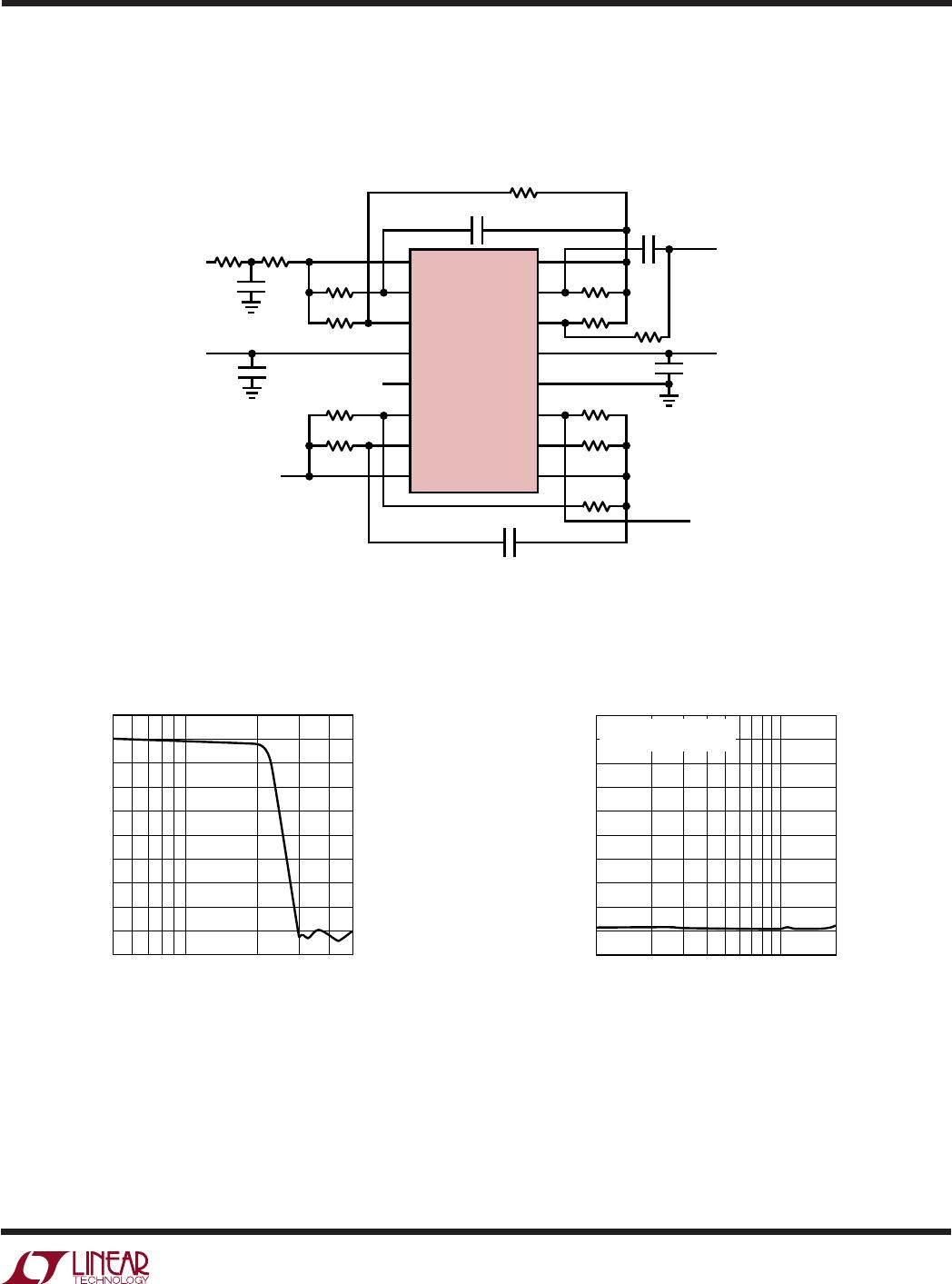
Dual 5th Order Lowpass “Elliptic” Filter
R
Q1
R
Q1
R
IN1B
R
IN1A
V
IN1
V
IN2
R
Q2
C
IN2
R
IN2
R
IN2
C
IN2
R
Q2
R22
R22
0.1µF
V
OUT2
V
OUT1
5V –5V
R21
R21
LTC1562
INVB
V1B
V2B
V
+
SHDN
V2A
V1A
INVA
20
19
18
16
15
13
12
11
INVC
V1C
V2C
V
–
AGND
V2D
V1D
INVD
1
2
3
5
6
8
9
10
0.1µF
C
IN1
R
IN1B
R
IN1A
C
IN1
1562 TA15a
SCHEMATIC INCLUDES PIN NUMBERS FOR 20-PIN PACKAGE.
PINS 4, 7, 14, 17 (NOT SHOWN) ALSO CONNECT TO V
–
Construction and Instrumentation Cautions
100dB rejections at hundreds of kilohertz require electri-
cally clean, compact construction, with good grounding
and supply decoupling, and minimal parasitic capaci-
tances in critical paths (such as Operational Filter block
INV inputs). In a circuit with 5k resistances trying for
100dB rejection at 100kHz, a stray coupling of 0.003pF
around the signal path can preclude the 100dB. (By
comparison, the stray capacitance between two adjacent
pins of an IC can be 1pF or more.) Also, high quality supply
bypass capacitors of 0.1µF near the chip provide good
decoupling from a clean, low inductance power source.
But several inches of wire (i.e., a few microhenrys of
inductance) from the power supplies, unless decoupled
by substantial capacitance (≥10µF) near the chip, can
cause a high-Q LC resonance in the hundreds of kHz in the
chip’s supplies or ground reference, impairing stopband
rejection and other specifications at those frequencies. In
demanding filter circuits we have often found that a
compact, carefully laid out printed circuit board with good
ground plane makes a difference of 20dB in both stopband
rejection and distortion performance. Highly selective
circuits can even exhibit these issues at frequencies well
below 100kHz. Finally, equipment to measure filter perfor-
mance can itself introduce distortion or noise floors;
checking for these limits with a wire replacing the filter is
a prudent routine procedure.
f
C
(Hz) R
IN1A
R
IN1B
C
IN1
R
Q1
R21 R
IN2
C
IN2
R
Q2
R22
100k 5.9k 7.5k 680pF 28k 7.5k 6.34k 68pF 9.31k 11.3k
75k 8.06k 15.4k 560pF 36.5k 13.3k 11.3k 68pF 12.7k 20k
50k 16.9k 35.7k 390pF 56.2k 30.1k 25.5k 68pF 18.7k 44.2k
Amplitude Response
FREQUENCY (kHz)
–120
–60
–80
–100
20
0
–20
–40
1562 TA15b
GAIN (dB)
10
1000
100
f
C
= 100kHz
TYPICAL APPLICATIONS
U
(Advanced)