MAX1108/MAX1109
Single-Supply, Low-Power,
2-Channel, Serial 8-Bit ADCs
_______________________________________________________________________________________ 7
ELECTRICAL CHARACTERISTICS—MAX1109 (continued)
(V
DD
= +4.5V to +5.5V; unipolar input mode; COM = GND, f
SCLK
= 500kHz, external clock (50% duty cycle); 10 clocks/conversion
cycle (50ksps); 1µF capacitor at REF, external +4.096V reference at REF; T
A
= T
MIN
to T
MAX
; unless otherwise noted. Typical values
are at T
A
= +25°C.)
CONDITIONS
External reference
Internal reference (Note 11)
µs20
ns200t
CL
SCLK Pulse Width Low
ms12
t
WAKE
Wake-Up Time
ns0t
CSH
CS to SCLK Rise Hold
ns100t
CSS
CS to SCLK Rise Setup
ns200t
CH
SCLK Pulse Width High
UNITSMIN TYP MAXSYMBOLPARAMETER
Note 1: Relative accuracy is the deviation of the analog value at any code from its theoretical value after the full-scale range has
been calibrated.
Note 2: See Typical Operating Characteristics.
Note 3: V
REF
= +2.048V (MAX1108), V
REF
= +4.096V (MAX1109), offset nulled.
Note 4: Common-mode range (CH0, CH1, COM) GND to V
DD
.
Note 5: Conversion time defined as the number of clock cycles times the clock period; clock has 50% duty cycle (Figures 6 and 8).
Note 6: REF supplies typically 2.5mA under normal operating conditions.
Note 7: External load should not change during the conversion for specified accuracy.
Note 8: Power consumption with CMOS levels.
Note 9: Power-down test performed using the following sequence 1) SHDN 5bit = 0 in the configuration register; 2) Wait for 10
SCLK cycles to complete current conversion; 3) Measure shutdown current with CS, SCLK, D
IN
= V
DD
or GND.
Note 10: Measured as V
FS
(2.7V) - V
FS
(3.6V) for MAX1108, and measured as V
FS
(4.5V) - V
FS
(5.5V) for MAX1109.
Note 11: 1µF at REF, internal reference settling to 0.5LSB.
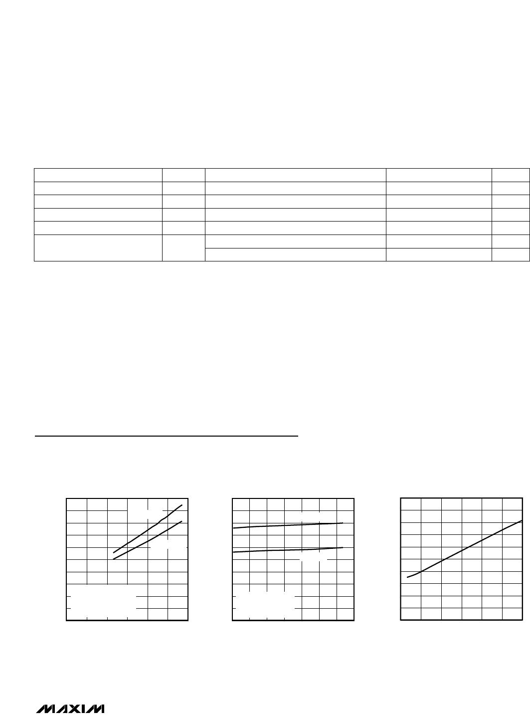
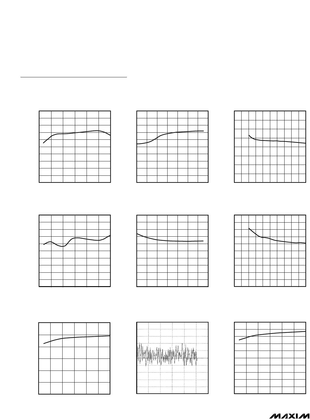
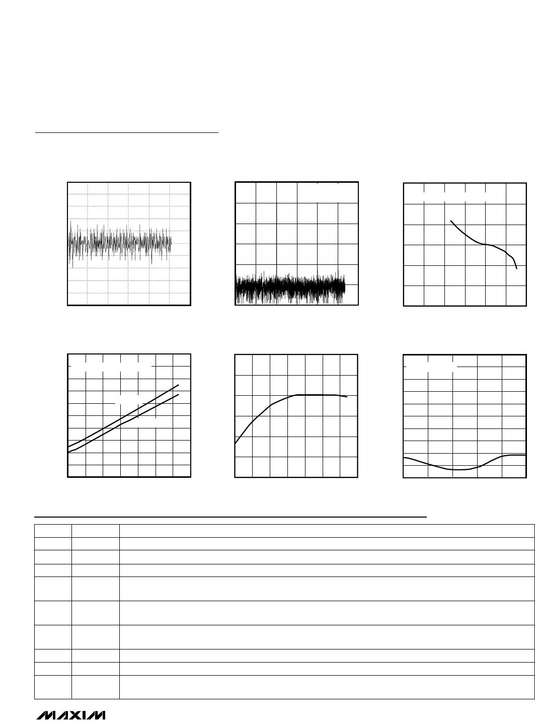
Typical Operating Characteristics
(V
DD
= +3.0V (MAX1108), V
DD
= +5.0V (MAX1109); external conversion mode; f
SCLK
= 500kHz; 50ksps; external reference; 1µF at
REF; T
A
= +25°C; unless otherwise noted.)