MXLRT100KP260A

MRT100KP40A – MRT100KP400CA(e3)
Available
Unidirectional and Bidirectional Transient
Voltage Suppressor (TVS) Device
Screening in
reference to
MIL-PRF-19500
available
DESCRIPTION
These MRT100KP40A – MRT100KP400CA high reliability devices protect against dangerous
high-voltage, short term transients such as those caused the the secondary effects of lightning
per IEC61000-4-5 (see protection classes below) and RTCA/DO-160. They also protect
against voltage spikes caused by inductive load switching, induced RFI, and ESD or EFT per
IEC61000-4-2 and IEC61000-4-4. Clamping time is nearly instantaneous at < 5ns.
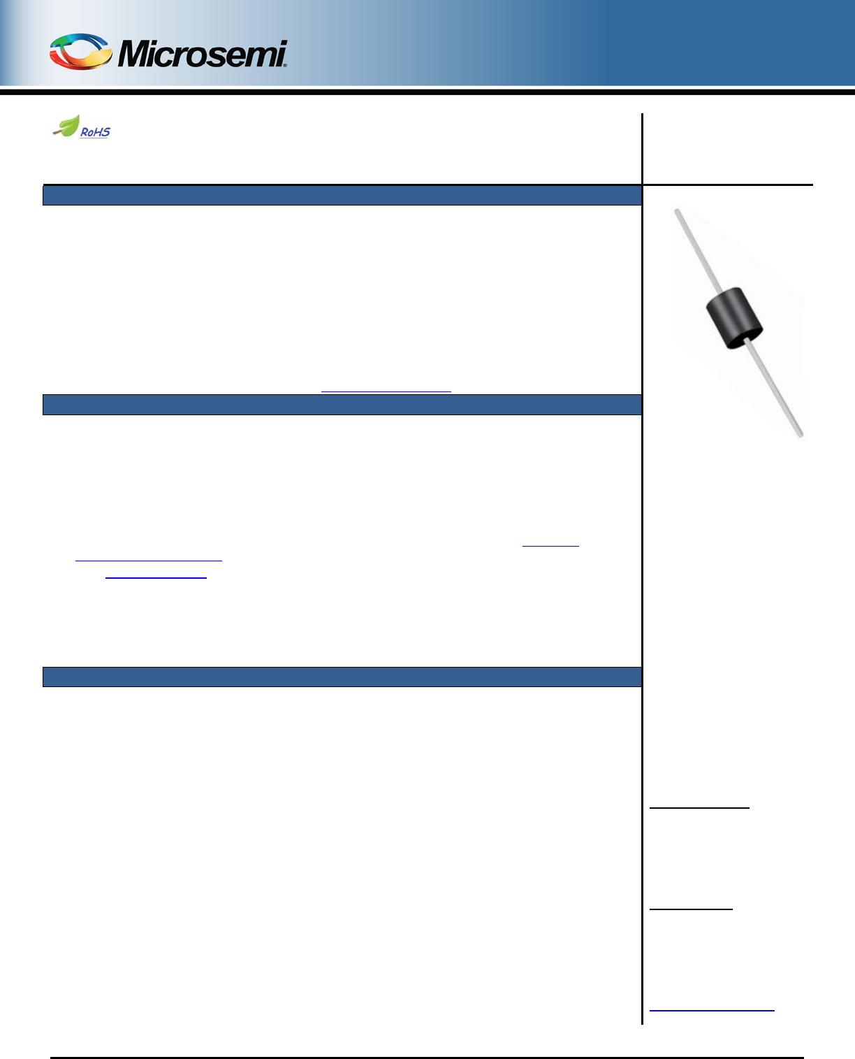
DO-204AR
Package
Important: For the latest information, visit our website http://www.microsemi.com.
FEATURES
Available in both unidirectional and bidirectional configurations
Suppresses transients up to 100 kW @ 6.4/69 µs
Fast response with less than 5 ns turn-on time
Preferred 100 kW TVS for aircraft power bus protection
3σ lot norm screening performed on standby current I
D
100% surge tested devices
Multiple screening levels in reference to MIL-PRF-19500 are available. Refer to Hirel Non-
Hermetic Product Portfolio for more details on the screening options.
(See part nomenclature for all options.)
High reliability controlled devices have wafer fabrication and assembly lot traceability
Moisture classification is level 1 with no dry pack required per IPC/JEDEC J-STD-020B
RoHS compliant versions are available
APPLICATIONS / BENEFITS
Economical TVS series for thru-hole mounting
Protection from high power switching transients, induced RF, and lightning threats with
comparatively small package size (0.25 inch diameter)
Protection from ESD and EFT per IEC61000-4-2 and IEC61000-4-4
Pin injection protection per RTCA/DO-160 up to Level 4 for Waveform 4 (6.4/69 μs) on all devices
Pin injection protection per RTCA/DO-160 up to Level 5 for Waveform 4 (6.4/69 μs) on device types
MRT100KP33A or CA up to MRT100KP260A or CA
Pin injection protection per RTCA/DO-160 up to Level 3 for Waveform 5A (40/120 μs) on all devices
Pin injection protection per RTCA/DO-160 up to Level 4 for Waveform 5A (40/120 μs) on device
types MRT100KP33A or CA up to MRT100KP64A or CA
Consult Factory for other voltages with similar Peak Pulse Power (P
PP
) capabilities
MSC – Lawrence
6 Lake Street,
Lawrence, MA 01841
1-800-446-1158 or
(978) 620-2600
Fax: (978) 689-0803
MSC Ireland
Gort Road Business Park,
Ennis, Co. Clare, Ireland
Tel: +353 (0) 65 6840044
Fax: +353 (0) 65 6822298
Website:
www.microsemi.com
RF01012, Rev. C (15/06/15) ©2015 Microsemi Corporation Page 1 of 7
MRT100KP40A – MRT100KP400CA(e3)
MAXIMUM RATINGS @ 25 ºC unless otherwise noted
Parameters/Test Conditions
Symbol
Value
Unit
Junction and Storage Temperature
T
J
and
T
STG
-65 to +150
o
C
Thermal Resistance, Junction to Lead @ 3/8 inch (10 mm)
lead length from body
R
ӨJL
17.5
o
C/W
Thermal Resistance, Junction to Ambient
(1)
R
ӨJA
77.5
o
C/W
Peak Pulse Power Dissipation
(2)
µ
P
PP
100
kW
Steady-State Power Dissipation @ T
A
= 25 ºC
P
D
7
1.61
(1)
W
T
clamping
(0 volts to V
(
BR)
min, theoretical)
< 100
< 5
ps
ns
Surge Peak Forward Current
(2)
I
FSM
250
A
Solder Temperature @ 10 s
260
o
C
Notes: 1. When mounted on FR4 PC board with 4 mm
2
copper pads (1 oz) and track width 1 mm, length 25 mm.
2. At 8.3 ms half-sine wave (unidirectional only).
MECHANICAL and PACKAGING
CASE: Void-free transfer molded thermosetting epoxy body meeting UL94V-0.
TERMINALS: Tin-lead or RoHS compliant annealed matte-tin plating. Solderable per MIL-STD-750, method 2026.
MARKING: Part number
POLARITY: Cathode indicated by band. No cathode band on bidirectional devices.
TAPE & REEL option: Standard per EIA-296 (add “TR” suffix to part number). Consult factory for quantities.
WEIGHT: Approximately 1.7 grams
See Package Dimensions
on last page.
PART NOMENCLATURE
M RT 100 K P 40 C A (e3)
Reliability Level
M
MA
MX
MXL
(*See
Hirel Non-Hermetic
Product Portfolio)
RTCA/DO-160 Rated
Peak Pulse Power
Kilowatt Rating
Encapsulated Plastic
Package
RoHS Compliance
e3 = RoHS compliant
Blank = non-RoHS compliant
Voltage Tolerance
A = 5% tolerance level
Blank = 10% tolerance
Polarity
C = Bi-directional
Blank = Unidirectional
Stand-off Voltage Rating
(see Electrical Characteristics
table)
RF01012, Rev. C (15/06/15) ©2015 Microsemi Corporation Page 2 of 7
MRT100KP40A – MRT100KP400CA(e3)
SYMBOLS & DEFINITIONS
Symbol
Definition
α
V(BR)
Temperature Coefficient of Breakdown Voltage: The change in breakdown voltage divided by the change in
temperature that caused it expressed in %/°C or mV/°C.
V
WM
Working Standoff Voltage: The maximum-rated value of dc or repetitive peak positive cathode-to-anode voltage that
may be continuously applied over the standard operating temperature.
P
PP
Peak Pulse Power. The rated random recurring peak impulse power or rated nonrepetitive peak impulse power. The
impulse power is the maximum-rated value of the product of I
PP
and V
C
.
V
(
BR)
Breakdown Voltage: The voltage across the device at a specified current I
(BR)
in the breakdown region.
I
D
Standby Current: The current through the device at rated stand-off voltage.
I
PP
Peak Impulse Current: The maximum rated random recurring peak impulse current or nonrepetitive peak impulse
current that may be applied to a device. A random recurring or nonrepetitive transient current is usually due to an
external cause, and it is assumed that its effect will have completely disappeared before the next transient arrives.
V
C
Clamping Voltage: The voltage across the device in a region of low differential resistance during the application of an
impulse current (I
PP
) for a specified waveform.
I
(BR)
Breakdown Current: The current used for measuring Breakdown Voltage V
(BR)
RF01012, Rev. C (15/06/15) ©2015 Microsemi Corporation Page 3 of 7

MXLRT100KP260A

Mfr. #:
Manufacturer:
Microchip / Microsemi
Description:
TVS Diodes / ESD Suppressors Hi Rel TVS
Lifecycle:
New from this manufacturer.
Delivery:
DHL FedEx Ups TNT EMS
Payment:
T/T Paypal Visa MoneyGram Western Union