MIC5206-3.0YMM

Micrel, Inc. MIC5206
May 2006
7
M9999-051506
(408) 955-1690
Typical Characteristics
0.0001
0.001
0.01
0.1
1
10
1E+11E+2 1E+3 1E+4 1E+51E+6 1E+7
(ESIO/V )zH
FREQUENCY (Hz)
Noise Performance
10mA
1mA
100mA
10
100
1k
10k 100k 1M 10M
V
OUT
= 5V
C
OUT
= 10µF
electrolytic
0.0001
0.001
0.01
0.1
1
10
1E+11E+2 1E+3 1E+4 1E+51E+6 1E+7
(ESIO/V )zH
FREQUENCY (Hz)
Noise Performance
10mA
1mA
100mA
10
100
1k
10k 100k 1M 10M
V
OUT
= 5V
C
OUT
= 22µF
tantalum
C
BYP
= 10nF
0.0001
0.001
0.01
0.1
1
10
1E+11E+2 1E+3 1E+4 1E+51E+6 1E+
7
(ESIO/V )zH
FREQUENCY (Hz)
Noise Performance
10mA
1mA
100mA
10
100
1k
10k 100k 1M 10M
V
OUT
= 5V
C
OUT
= 10µF
electrolytic
C
BYP
= 100pF
0.0001
0.001
0.01
0.1
1
10
1E+11E+2 1E+3 1E+4 1E+51E+6 1E+7
(ESIO/V )zH
FREQUENCY (Hz)
Noise Performance
10mA
1mA
100mA
10
100
1k
10k 100k 1M 10M
V
OUT
= 5V
C
OUT
= 10µF
electrolytic
C
BYP
= 1nF
0.0001
0.001
0.01
0.1
1
10
1E+11E+2 1E+3 1E+4 1E+51E+6 1E+7
(ESIO/V )zH
FREQUENCY (Hz)
Noise Performance
10mA
1mA
100mA
10
100
1k
10k 100k 1M 10M
V
OUT
= 5V
C
OUT
= 10µF
electrolytic
C
BYP
= 1nF
0
40
80
120
160
200
240
280
320
0 40 80 120 160
)Vm(EGATLOVTUOPORD
OUTPUT CURRENT (mA)
Dropout Voltage
vs. Output Current
+125°C
+25°C
–4C
Micrel, Inc. MIC5206
May 2006
8
M9999-051506
(408) 955-1690
Application Information
Enable/Shutdown
Forcing EN (enable/shutdown) high (> 2V) enables the
regulator. EN is compatible with CMOS logic gates.
If the enable/shutdown feature is not required, connect
EN (enable) to IN (supply input). Refer to the text with
Figures 1aand 2.
Input Capacitor
A 1µF capacitor should be placed from IN to GND if
there is more than 10 inches of wire between the input
and the ac filter capacitor or if a battery is used as the
input.
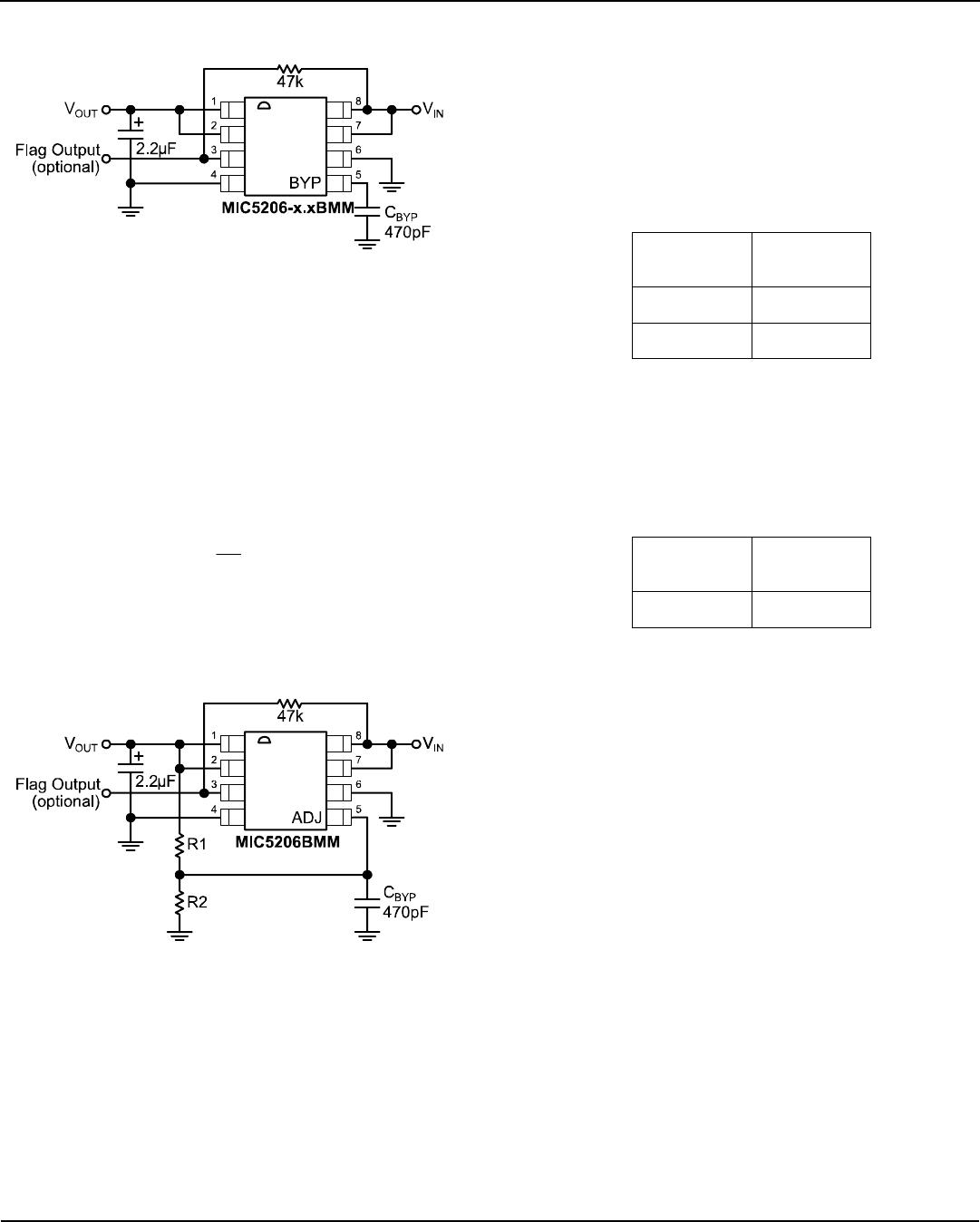
Reference Bypass Capacitor
BYP (reference bypass) is connected to the internal
voltage reference. A 470pF capacitor (C
BYP
) connected
from BYP to GND quiets this reference, providing a
significant reduction in output noise. See Figure 2. C
BYP
reduces the regulator phase margin; when using C
BYP
,
output capacitors of 2.2µF or greater are generally
required to maintain stability.
The start-up speed of the MIC5206 is inversely
proportional to the size of the reference bypass
capacitor. Applications requiring a slow ramp-up of
output voltage should consider larger values of C
BYP
.
Likewise, if rapid turn-on is necessary, consider omitting
C
BYP
.
If output noise is not a major concern, omit C
BYP
and
leave BYP open.
Output Capacitor
An output capacitor is required between OUT and GND
to prevent oscillation. The minimum size of the output
capacitor is dependent upon whether a reference bypass
capacitor is used. 1.0µF minimum is recommended
when C
BYP
is not used (see Figure 2). 2.2µF minimum is
recommended when C
BYP
is 470pF (see Figure 2).
Larger values improve the regulator’s transient
response. The output capacitor value may be increased
without limit.
The output capacitor should have an ESR (effective
series resistance) of about 5 or less and a resonant
frequency above 1MHz. Most tantalum or aluminum
electrolytic capacitors are adequate; film types will work,
but are more expensive. Since many aluminum
electrolytics have electrolytes that freeze at about
–30°C, solid tantalums are recommended for operation
below –25°C.
At lower values of output current, less output
capacitance is required for output stability. The capacitor
can be reduced to 0.47µF for current below 10mA or
0.33µF for currents below 1mA.
No-Load Stability
The MIC5205 will remain stable and in regulation with no
load (other than the internal voltage divider) unlike many
other voltage regulators. This is especially important in
CMOS RAM keep-alive applications.
Error Flag Output
The error flag is an open-collector output and is active
(low) when an undervoltage of approximately 5% below
the nominal output voltage is detected. A pull-up resistor
from IN to FLAG is shown in all schematics.
If an error indication is not required, FLAG may be left
open and the pull-up resistor may be omitted.
Enable Pin Ramp and the Error Flag
To prevent indeterminate behavior on the error flag
during power down of the device, ensure that the fall
time of the enable pin signal, from logic high to logic low,
is faster than 100µs.
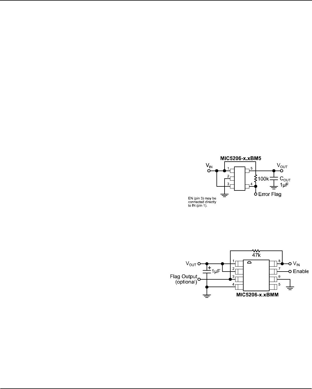
Fixed Regulator Applications
Figure 1a. Low-Noise Fixed Voltage Application
EN (pin 3) is shown connected to IN (pin 1) for an
application where enable/shutdown is not required. The
error flag is shown with a 100k pull-up resistor.
Figure 1b. Low-Noise Fixed Voltage Application
Figure 1b is an example of a basic configuration where
the lowest-noise operation is not required. C
OUT
= 1µF
minimum. The error flag is shown with a 47k pull-up
resistor.
Micrel, Inc. MIC5206
May 2006
9
M9999-051506
(408) 955-1690
Ultra-Low-Noise Application
Figure 2. Ultra-Low-Noise Fixed Voltage Application
Figure 2 includes a 470pF capacitor for low-noise
operation and shows EN (pin 7) connected to IN (pin 8)
for an application where enable/shutdown is not
required. The error flag is shown with a 47k pull-up
resistor.
Adjustable Regulator Applications
Figure 3 shows the MIC5206BMM adjustable output
voltage configuration. Two resistors set the output
voltage. The formula for output voltage is:
+×= 1
R1
R2
1.242VV
OUT
Resistor values are not critical because ADJ (adjust) has
a high input impedance, but for best results use resistors
of 470k or less. A capacitor from ADJ to ground
provides greatly improved noise performance.
Figure 3. Ultra-Low-Noise Adjustable Voltage Application
Figure 3 also includes a 470pF capacitor for lowest-
noise operation and shows EN (pin 7) connected to IN
(pin 8) for an application where enable/shutdown is not
required. C
OUT
= 2.2µF minimum. The error flag is shown
with a 47k pull-up resistor.
Thermal Considerations
Layout
The MIC5206-x.xBM5 (5-pin SOT-23 package) has the
following thermal characteristics when mounted on a
single layer copper-clad printed circuit board.
Multilayer boards having a ground plane, wide traces
near the pads, and large supply bus lines provide better
thermal conductivity.
PC Board
Dielectric
θ
JA
FR4 220°C/W
Ceramic 200°C/W
SOT-23-5 Thermal Characteristics
The “worst case” value of 220°C/W assumes no ground
plane, minimum trace widths, and a FR4 material board.
The MIC5206-xxBMM (8-pin MSOP) has a thermal
resistance of 200°C/W when mounted on a FR4 board
with minimum trace widths and no ground plane.
PC Board
Dielectric
θ
JA
FR4 200°C
MSOP Thermal Characteristics
Nominal Power Dissipation and Die Temperature
The MIC5206-x.xBM5 at a 25°C ambient temperature
will operate reliably at over 450mW power dissipation
when mounted in the “worst case” manner described
above. At an ambient temperature of 40°C, the device
may safely dissipate over 380mW. These power levels
are equivalent to a die temperature of 125°C, the
maximum operating junction temperature for the
MIC5206.
For additional heat sink characteristics, please refer to
Micrel Application Hint 17, “Calculating P.C. Board Heat
Sink Area For Surface Mount Packages”.

MIC5206-3.0YMM

Mfr. #:
Manufacturer:
Microchip Technology / Micrel
Description:
LDO Voltage Regulators 150mA 1% Low Noise LDO w/Flag
Lifecycle:
New from this manufacturer.
Delivery:
DHL FedEx Ups TNT EMS
Payment:
T/T Paypal Visa MoneyGram Western Union