2-Terminal IC
Temperature Transducer
Data Sheet
AD590
Rev. G Document Feedback
Information furnished by Analog Devices is believed to be accurate and reliable. However, no
responsibility is assumed by Analog Devices for its use, nor for any infringements of patents or other
rights of third parties that may result from its use. Specifications subject to change without notice. No
license is granted by implication or otherwise under any patent or patent rights of Analog Devices.
Trademarks and registered trademarks are the property of their respective owners.
One Technology Way, P.O. Box 9106, Norwood, MA 02062-9106, U.S.A.
Tel: 781.329.4700 ©2013 Analog Devices, Inc. All rights reserved.
Technical Support www.analog.com
FEATURES
Linear current output: 1 μA/K
Wide temperature range: −55°C to +150°C
Probe-compatible ceramic sensor package
2-terminal device: voltage in/current out
Laser trimmed to ±0.5°C calibration accuracy (AD590M)
Excellent linearity: ±0.3°C over full range (AD590M)
Wide power supply range: 4 V to 30 V
Sensor isolation from case
Available in 2-lead FLATPACK, 4-lead LFCSP, 3-pin TO-52,
8-lead SOIC, and die form
GENERAL DESCRIPTION
The AD590 is a 2-terminal integrated circuit temperature trans-
ducer that produces an output current proportional to absolute
temperature. For supply voltages between 4 V and 30 V, the device
acts as a high impedance, constant current regulator passing
1 μA/K. Laser trimming of the chip’s thin-film resistors is used
to calibrate the device to 298.2 μA output at 298.2 K (25°C).
The AD590 should be used in any temperature-sensing
application below 150°C in which conventional electrical
temperature sensors are currently employed. The inherent
low cost of a monolithic integrated circuit combined with the
elimination of support circuitry makes the AD590 an attractive
alternative for many temperature measurement situations.
Linearization circuitry, precision voltage amplifiers, resistance
measuring circuitry, and cold junction compensation are not
needed in applying the AD590.
In addition to temperature measurement, applications include
temperature compensation or correction of discrete components,
biasing proportional to absolute temperature, flow rate measure-
ment, level detection of fluids and anemometry. The AD590 is
available in die form, making it suitable for hybrid circuits and
fast temperature measurements in protected environments.
The AD590 is particularly useful in remote sensing applications.
The device is insensitive to voltage drops over long lines due to
its high impedance current output. Any well-insulated twisted
pair is sufficient for operation at hundreds of feet from the
receiving circuitry. The output characteristics also make the
AD590 easy to multiplex: the current can be switched by a
CMOS multiplexer, or the supply voltage can be switched by a
logic gate output.
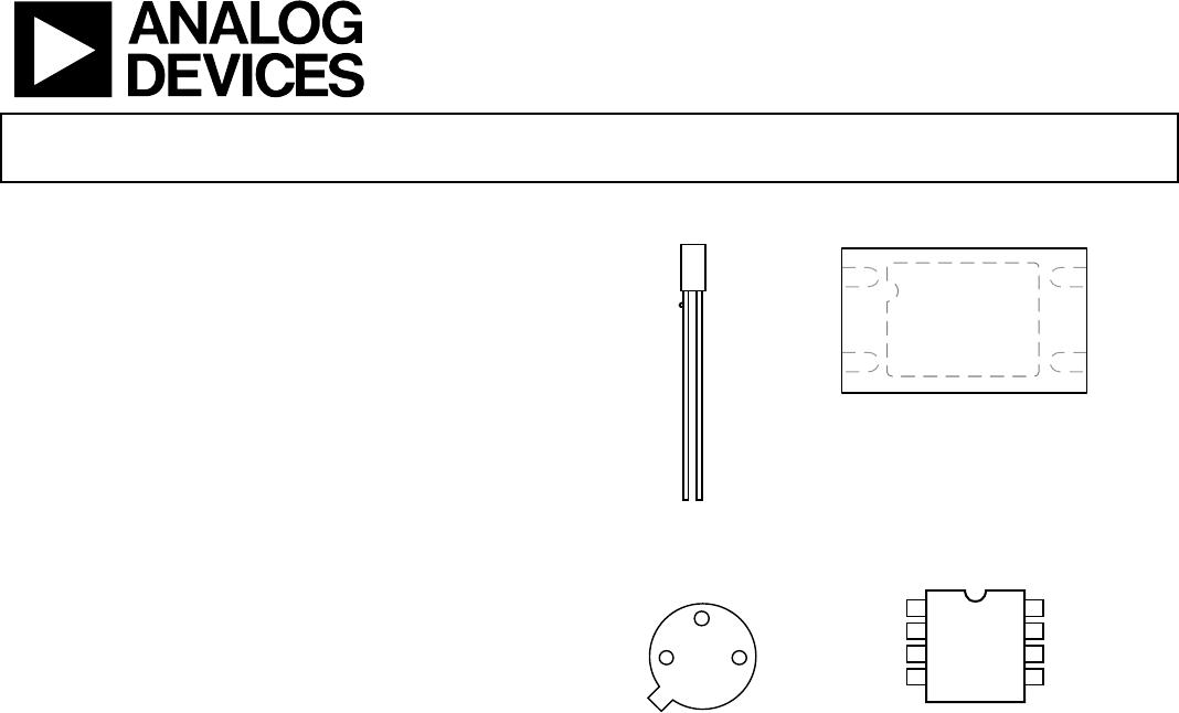
PIN CONFIGURATIONS
Figure 1. 2-Lead
FLATPACK
Figure 2. 4-Lead LFCSP
Figure 3. 3-Pin TO-52
Figure 4. 8-Lead SOIC
PRODUCT HIGHLIGHTS
1. The AD590 is a calibrated, 2-terminal temperature sensor
requiring only a dc voltage supply (4 V to 30 V). Costly
transmitters, filters, lead wire compensation, and lineari-
zation circuits are all unnecessary in applying the device.
2. State-of-the-art laser trimming at the wafer level in
conjunction with extensive final testing ensures that
AD590 units are easily interchangeable.
3. Superior interface rejection occurs because the output is a
current rather than a voltage. In addition, power
requirements are low (1.5 mW @ 5 V @ 25°C). These
features make the AD590 easy to apply as a remote sensor.
4. The high output impedance (>10 MΩ) provides excellent
rejection of supply voltage drift. For instance, changing the
power supply from 5 V to 10 V results in only a 1 μA
maximum current change, or 1°C equivalent error.
5. The AD590 is electrically durable: it withstands a forward
voltage of up to 44 V and a reverse voltage of 20 V.
Therefore, supply irregularities or pin reversal does not
damage the device.
00533-024
+–
1
+
2V–
4NC
3NC
00533-104
AD590
TOP VIEW
(Not to Scale)
PIN 5 (EXPOSED PAD)
NOTES
1. NC = NO CONNECT. THE NC PIN IS NOT
BONDED TO THE DIE INTERNALLY.
. TO ENSURE CORRECT OPERATION, THE
EXPOSED PAD (EP) SHOULD BE LEFT FLOATING.
0533-025
+
00533-001
NC = NO CONNECT
TOP VIEW
(Not to Scale)
NC
1
V+
2
V–
3
NC
4
NC
NC
NC
NC
8
7
6
5