© KEMET Electronics Corporation • P.O. Box 5928 • Greenville, SC 29606 (864) 963-6300 • www.kemet.com CC101_COMM_SMD • 11/25/2013
60
One world. One KEMET
Overview
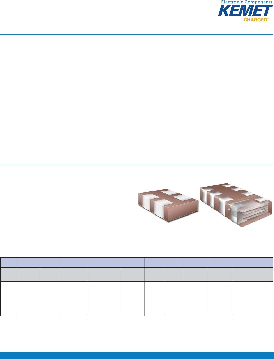
KEMET’s Ceramic Chip Capacitor Array in X7R dielectric is an
advanced passive technology where multiple capacitor elements
are integrated into one common monolithic structure. Array
technology promotes reduced placement costs and increased
throughput. This is achieved by alternatively placing one device
rather than two or four discrete devices. Use of capacitor arrays
also saves board space which translates into increased board
density and more functions per board. Arrays consume only a
portion of the space required for standard chips resulting in savings
in inventory and pick/place machine positions.
KEMET’s X7R dielectric features a 125°C maximum operating
temperature and is considered “temperature stable.” The
Electronics Industries Alliance (EIA) characterizes X7R dielectric
DVD&ODVV,,PDWHULDO&RPSRQHQWVRIWKLVFODVVL¿FDWLRQDUH¿[HG
ceramic dielectric capacitors suited for bypass and decoupling
applications or for frequency discriminating circuits where Q and
stability of capacitance characteristics are not critical. X7R exhibits
a predictable change in capacitance with respect to time and
voltage and boasts a minimal change in capacitance with reference
to ambient temperature. Capacitance change is limited to ±15%
from -55°C to +125°C.
KEMET automotive grade array capacitors meet the demanding
$XWRPRWLYH(OHFWURQLFV&RXQFLOV$(&±4TXDOL¿FDWLRQ
requirements.
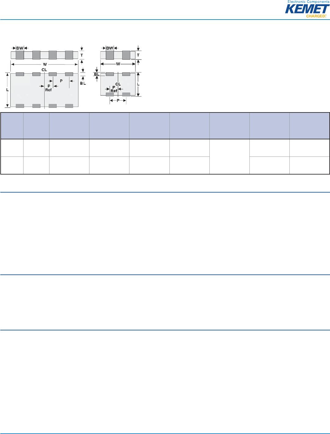
Surface Mount Multilayer Ceramic Chip Capacitors (SMD MLCCs)
Capacitor Array, X7R Dielectric, 10 – 200 VDC
(Commercial & Automotive Grade)
Ordering Information
CA 06 4 C 104 K 4 R A C TU
Ceramic
Array
Case Size
(L" x W")
1
Number of
Capacitors
6SHFL¿FDWLRQ
Series
Capacitance
Code (pF)
Capacitance
Tolerance
Voltage Dielectric
Failure Rate/
Design
Termination
Finish
2
Packaging/Grade
(C-Spec)
3
05 = 0508
06 = 0612
2 = 2
4 = 4
C = Standard
X = Flexible
Termination
6LJQL¿FDQW
Digits + Number
of Zeros
J = ±5%
K = ±10%
M = ±20%
8 = 10 V
4 = 16 V
3 = 25 V
5 = 50 V
1 = 100 V
2 = 200 V
R = X7R A = N/A C = 100%
Matte Sn
L = SnPb
(5%
minimum)
Blank = Bulk
TU = 7" Reel
Unmarked
TM = 7" Reel Marked
AUTO = Automotive
Grade
1
All previous reference to metric case dimension "1632" has been replaced with an inch standard reference of "0612". Please reference all new designs using the
"0612" nomenclature. "CA064" replaces "C1632" in the ordering code.
2
$GGLWLRQDOWHUPLQDWLRQ¿QLVKRSWLRQVPD\EHDYDLODEOH&RQWDFW.(0(7IRUGHWDLOV
2,3
6Q3EWHUPLQDWLRQ¿QLVKRSWLRQLVQRWDYDLODEOHRQDXWRPRWLYHJUDGHSURGXFW
3
Additional reeling or packaging options may be available. Contact KEMET for details.
%HQHÀWV
• -55°C to +125°C operating temperature range
• Saves both circuit board and inventory space
• Reduces placement costs and increases throughput
• RoHS Compliant
• EIA 0508 (2-element) and 0612 (4-element) case sizes
• DC voltage ratings of 10 V, 16 V, 25 V, 50 V, 100 V, and 200 V