2
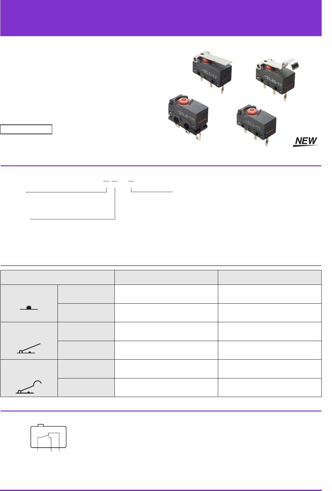
D2FD Dust Proof Ultra Subminiature Basic Switch
Contact Specifications
Note: For more information on the minimum applicable load, refer to Using Micro Loads.
Ratings
Note: The rating values apply under the following test conditions.
1. Ambient temperature: 20 ± 2°C
2. Ambient humidity: 65 ± 5%
3. Operating frequency: 20 operations/min
Characteristics
Note: 1. The data given above are initial values.
2. The dielectric strength shown in the table indicates a value for models with a Separator.
3. For the pin plunger models, the above values apply for both the free position and total travel position. For the lever models, the values apply at the total travel
position. Contact opening or closing time is within 1 ms.
4. Consult your OMRON sales representative for testing conditions.
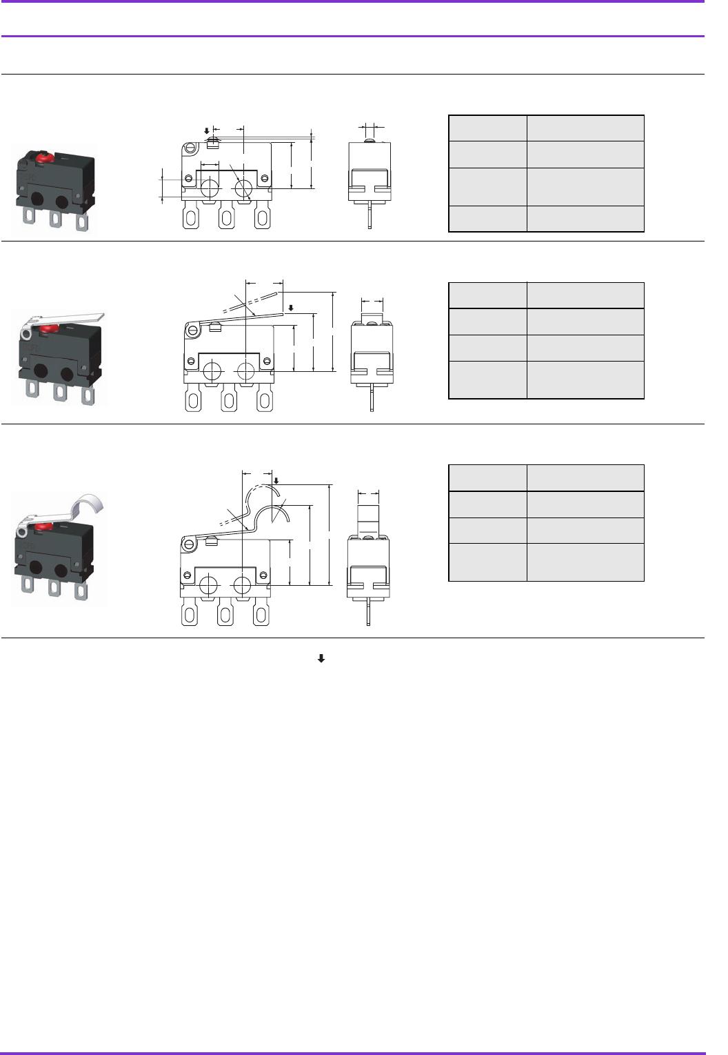
Terminals (Unit: mm)
Mounting Holes (Unit: mm)
● Solder Terminals
Item Model D2FD-2 models D2FD-01 models
Contact
Specification Crossbar
Material Silver alloy Gold alloy
Gap (standard value) 0.25 mm
Minimum applicable load (see note) 100 mA at 5 VDC 1 mA at 5 VDC
Model
Rated voltage
D2FD-2 models D2FD-01 models
Resistive load
125 VAC 2 A 0.1 A
30 VDC 2 A 0.1 A
Item Model D2FD-2 models D2FD-01 models
Operating speed 1 mm to 500 mm/s
Operating frequency
Mechanical 120 operations/min max.
Electrical 20 operations/min max
Insulation resistance 100 MΩ min. (at 500 VDC)
Contact resistance (initial value) 30 mΩ max. 100 mΩ max.
Dielectric strength (see note 2)
600 VAC 50/60 Hz 1 min between terminals of same polarity
1,500 VAC 50/60 Hz 1 min between current carrying metal parts and ground
1,500 VAC 50/60 Hz 1 min between each terminal and non-current carrying metal part
Vibration resistance (see note 3)
Malfunction 10 to 55 Hz, 1.5 mm double amplitude
Shock resistance (see note 3)
Destruction 1,000 m/s
2
max.
Malfunction 300 m/s
2
max.
Durability (see note 4)
Mechanical 300,000 operations min. (at 60 ops./min.)
Electrical 30,000 operations min. (at 20 ops./min.) 100,000 operations min. (at 20 ops./min.)
Degree of protection IP6X
Ambient operating temperature −20 to +70°C (at 60%RH max.) (with no icing)
Ambient operation humidity 85%RH max. (for +5 to +35°C)
Weight Approx. 0.7 g (pin plunger, PCB terminal models)
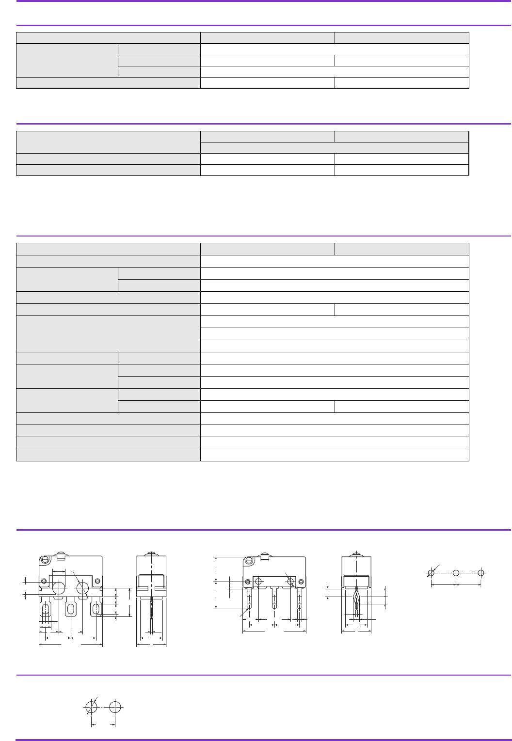
● Solder Terminals ● PCB Terminals
PCB Mounting Dimensions
(Reference)
1.5
2.4 Dia.
+0.1
–0.05
0.5
1.7
2.5
±0.1
1.2
0.4
12.8
±0.15
5.08
±0.15
5.08
±0.15
4.8
±0.1
4
5.7
2
4.4
6
2.2
2.4
+0.1
–0.05
Three, R0.8
1.25
±0.12
1.5
±0.12
1.1
±0.12
0.4
0.9
Two,1.2 Dia.
+0.12
0
5
±0.15
5.5
6
4.4
1.5
±0.1
3.15
6.5
±0.1
5.08
±0.15
5.08
±0.15
12.8
±0.15
1.6
5.08
±0.1
Three, 1.2
±0.05
Dia.
5.08
±0.1
Two, M2.3
4.8
±0.1