4
D2FD Dust Proof Ultra Subminiature Basic Switch
Precautions
Refer to General Information.
● Degree of Protection
• Do not use the Switch under the environment where it is
exposed to water.
The degree of protection is IP6X and the protection against
water is not defined.
• Prevent the Switch from coming into contact with oil and
chemicals. Otherwise, damage to or deterioration of Switch
materials may result.
• Do not use the Switch in areas where it is exposed to silicon
adhesives, oil, or grease, otherwise faulty contact may result
due to the generation of silicon oxide.
• The environment-resistant performance of the switch differs
depending on operating loads, ambient atmospheres, and
installation conditions, etc. Please perform an operating test of
the switch in advance under actual usage conditions.
● Terminal Connection
• When soldering a lead wire to the terminal, first insert the lead
wire conductor into the terminal hole and then perform solder-
ing. Make sure that the capacity of the soldering iron is 30 W
maximum and that the temperature of the soldering iron tip is
approximately 300°C. (350°C maximum.) Complete the sol-
dering within 3 s.
Using a switch with improper soldering may result in abnormal
heating, possibly resulting in burn.
Applying a soldering iron for more than 3 s or using one that is
rated at more than 30 W may deteriorate the switch character-
istics.
When using automatic soldering baths, we recommend solder-
ing at 260 ± 5°C within 5 seconds. Make sure that the liquid
surface of the solder does not flow over the edge of the board.
● Mounting
• Turn OFF the power supply before mounting or removing the
Switch, wiring, or performing maintenance or inspection. Fail-
ure to do so may result in electric shock or burning.
•
Use M2.3 mounting screws with plane washers or spring wash-
ers to securely mount the Switch. Tighten the screws to a torque
of 0.20 to 0.29 N
·
m {2.0 to 2.9 kgf
·
cm}. Exceeding the specified
torque may result in deterioration of the sealing or damage.
Mount the Switch onto a flat surface. Mounting on an uneven
surface may cause deformation of the Switch, resulting in
faulty operation or damage.
● Operating Body
• Use an operating body with low frictional resistance and of a
shape that will not interfere with the sealing rubber, otherwise
the plunger may be damaged or the sealing may deteriorate.
With the pin plunger models, set the Switch so that the plunger can
be pushed in from directly above. Since the plunger is covered with
a rubber cap, applying a force from lateral directions may cause
damage to the plunger or reduction in the sealing capability.
● Handing
• Do not handle the Switch in a way that may cause damage to the
sealing rubber.
• When handling the Switch, ensure that uneven pressure or, as
shown in the following diagram, pressure in a direction other than
the operating direction is not applied to the Actuator, otherwise
the Actuator or Switch may be damaged, or durability may be
decreased.
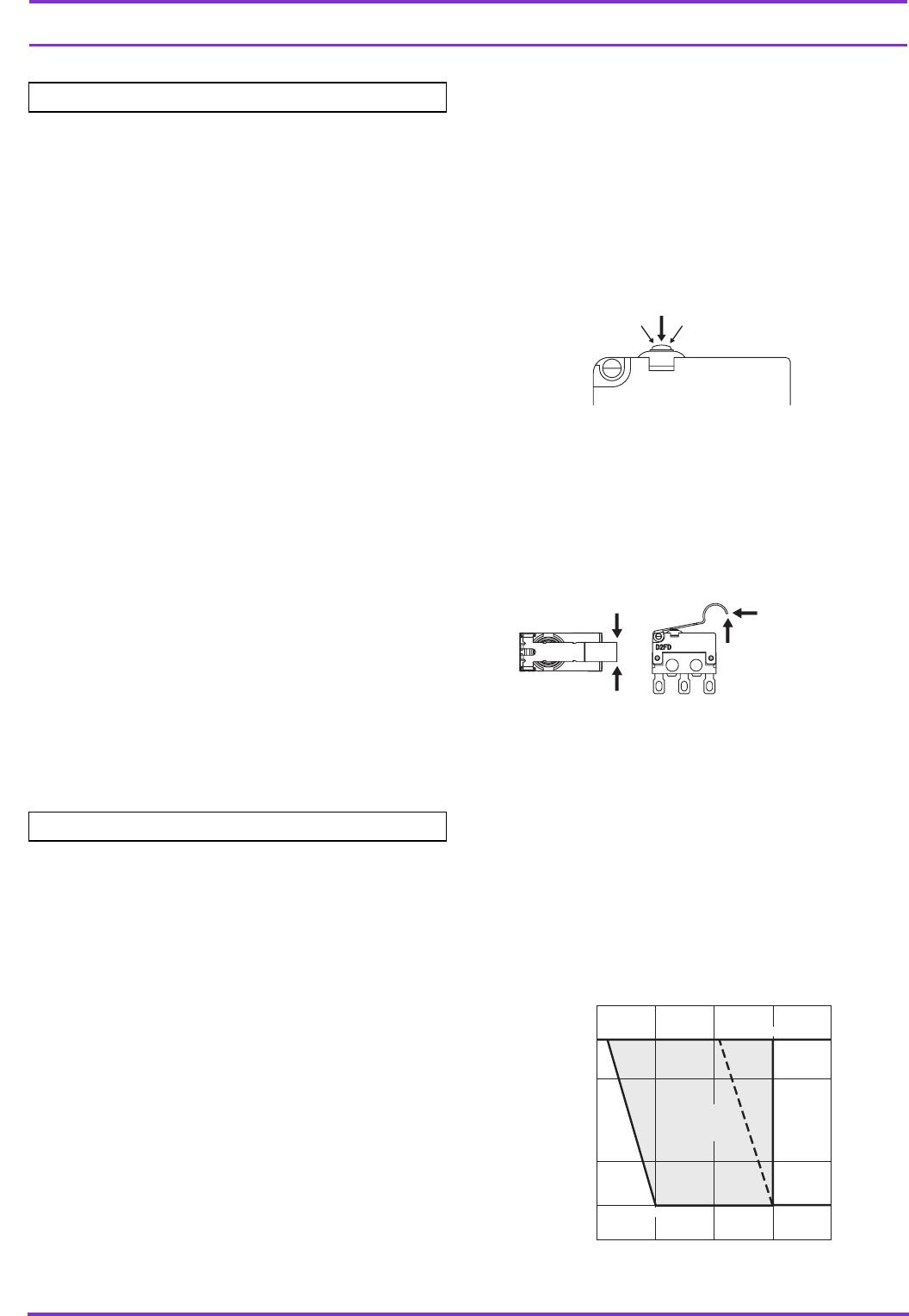
● Using Micro Loads
Using a model for ordinary loads to open or close the contact of
a micro load circuit may result in faulty contact. Use models that
operate in the following range. However, even when using micro
load models within the operating range shown below, if inrush
current occurs when the contact is opened or closed, it may
increase contact wear and so decrease durability. Therefore,
insert a contact protection circuit where necessary.
The minimum applicable load is the N-level reference value. This
value indicates the malfunction reference level for the reliability
level of 60% (λ 60). The equation, λ 60 = 0.5 × 10
-6
/operations
indicates that the estimated malfunction rate is less than 1/
2,000,000 operations with a reliability level of 60%.
Cautions
Correct Use
Correct
IncorrectIncorrect
Incorrect
Incorrect
Incorrect
Incorrect
30
24
12
5
0
1 10 100 1,000
Current (mA)
0.1
1 mA
Operating
range for
general-load
models
D2FD-2
16.6 mA0.16 mA 100 mA
Operating range
for micro load
models D2FD-01
Inoperable
range
Voltage (V)
