337
©2008 Littelfuse, Inc.
Revised: July 9, 2008
Teccor
®
brand Thyristors
Specifications are subject to change without notice.
Please refer to http://www.littelfuse.com for current information.
337
©2008 Littelfuse, Inc.
Teccor
®
brand Thyristors
Specifications are subject to change without notice.
Please refer to http://www.littelfuse.com for current information.
HTxxx & HTMxxx & STxxx Series
Standard Bidirectional DIAC Trigger
DIACs
HTxxx & HTMxxx & STxxx Series
The HTM, HT, and ST series of bilateral trigger DIACs offer
a range of voltage characteristics from 27V to 70V. A DIAC
semiconductor is a full-wave or bidirectional Thyristor. It is
triggered from a blocking state to a conduction state for
either polarity of applied voltage whenever the amplitude of
applied voltage exceeds the breakover voltage of the DIAC.
Description
Features & Benefits
t compliant
t#JMBUFSBMUSJHHFSJOHEFWJDF
t(MBTTQBTTJWBUFE
junctions
t8JEFWPMUBHFSBOHF
selections
t-POHUFSNSFMJBCJMJUZ
t1BSBNFUFSTUBCJMJUZ
t3FMJBCMFCBSSJFSBHBJOTU
junction contamination
ST Series:
t&QPYZ4.QBDLBHF
(DO-214)
t)JHIUFNQFSBUVSFTPMEFS
bonded die attachment
HTM/HT Series:
t.*/*.&-'%0USJHHFS
package
Schematic Symbol
Absolute Maximum Ratings
Symbol Parameter
Test Conditions
Min Max Unit
I
TRM
Pulse On-State Current
120PPS, T
A
≤ 40°C
pulse width = 10 μS
2
A
1. 5
(*)
T
S
Storage Temperature Range -40 +125 °C
T
J
Operating Junction Temperature -40 +125 °C
P
D(AV)
Device Power Dissipation T
A
= -40°C to +40°C
See Product
Selector Table
mW
(*)Only Applies to HT-60
Notes:
1. Service Dissipation (at T
A
= -40°C to +40°C): 250mW for DO-35 and MINIMELF/SOD-80
and 300mW for DO214
2. Above +40°C, Derate: 3.6mW/°C for DO-35 and MINIMELF/SOD-80
and 3mW/°C for DO214
DIACs are used to trigger Triacs and SCRs in phase control
circuits for lamp dimming, universal motor speed control,
and heat control. They are used also for triggering
transistors in solid state ballast lighting controls.
Applications
338
Revised: July 9, 2008
©2008 Littelfuse, Inc.
Teccor
®
brand Thyristors
Specifications are subject to change without notice.
Please refer to http://www.littelfuse.com for current information.
Specifications are subject to change without notice.
Please refer to http://www.littelfuse.com for current information.
Standard Bidirectional DIAC Trigger
HTxxx & HTMxxx & STxxx Series
Thermal Resistances
Symbol Description Test Conditions Value Unit
R
R(J-L)
Junction to Lead
Maximum Lead Temperature: 85°C DO-35 100 °C/W
Maximum Lead Temperature: 90°C DO-214 65* °C/W
Maximum Lead Temperature: 87°C MINIMELF 75 °C/W
R
R(J-A)
Junction to Ambient Free-Air DO-35 278 °C/W
* Mounted on 1 cm
2
copper foil surface; two-ounce copper foil
Electrical Characteristics (T
J
= 25°C, unless otherwise specified)
Symbol Description Test Conditions Min Max Unit
V
BO
Breakover/Trigger Voltage 50/60Hz Sine Wave
See Product
Selector Table
See Product
Selector Table
V
ΔV
BO
Breakover Voltage Symmetry +V
BO
to -V
BO
2
(Note 1)
V
V
BB
Δ Breakback Voltage
(Note 4)
V
BO
to V
10mA
5V
V
BO
to V
6mA
(*)
15 V
V
BB (DYN)
Dynamic Δ Breakback Voltage
(Notes 2 & 3)
120 PPS 10 V
I
BO
Breakover Current 50/60Hz Sine Wave 15 μA
(*) Only Applies to HT-60
Electrical Characteristic Notes:
1. Breakover voltage symmetry as close as 1V is available from the factory for
these products.
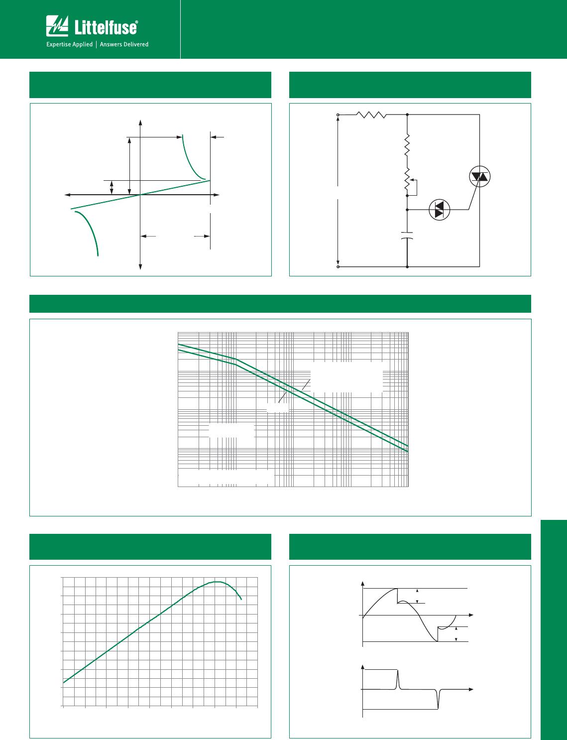
2. See Figure 4 and Figure 5 for test circuit and waveforms.
3. Typical switching time is 900 nano-seconds measured at I
PK
(Figure 4) across a
20 Ω resistor (Figure 5). Switching time is defined as rise time of I
PK
between the
10% to 90% points
4. See V-I Characteristics
Static Characteristics - Not Applicable
Product Selector
Part Number
Package Availability V
BO
MINIMELF DO-35 DO-214 MIN MAX
XX-32 HT-32 ST-32 27V 37V
XX-32A/ 5761 HT-32A 28V 36V
XX-32B/ 5761A HTM-32B HT-32B ST-32B 30V 34V
XX-34B — HT-34B ST-34B 32V 36V
XX-35 HT-35 ST-35 30V 40V
XX-36A/ 5762 HT-36A ST-36A 32V 40V
XX-36B — HT-36B ST-36B 34V 38V
XX-40 — HT-40 ST-40 35V 45V
XX-60 — HT-60 — 56V 70V
“XX” = HTM for MINIMELF
HT for DO-35
ST for DO-214
339
©2008 Littelfuse, Inc.
Revised: July 9, 2008
Teccor
®
brand Thyristors
Specifications are subject to change without notice.
Please refer to http://www.littelfuse.com for current information.
339
©2008 Littelfuse, Inc.
Teccor
®
brand Thyristors
Specifications are subject to change without notice.
Please refer to http://www.littelfuse.com for current information.
HTxxx & HTMxxx & STxxx Series
Standard Bidirectional DIAC Trigger
DIACs
Figure 1: V-I Characteristics
Figure 2: Typical DIAC/Triac Full-wave Phase Control
Circuit
120 V ac
60 Hz
Resistive Load
3.3 k
200 k
0.1 μF
100 V
Diac
Triac
MT2
MT1
G













Figure 3: Repetitive Peak On-state Current vs. Pulse Duration
12
4
000010004000200010040026
.001
.002
.003
.005
0.1
0.2
0.3
3.0
0.5
5.0
.01
0.02
0.03
0.05
1.0
10
2.0
Repetitive Peak On-state Current (I
TRM
) – Amps
Base Pulse Duration – μs
Safe Operating
Area
10 20 40 60 100
PULSE REPETITION RATE = 120 pps
T
A
= 40 ˚C
HT-60
HTM-32B
HT-32x, -34x, -35, -36x, -40
HT-5761, -5761A, -5762
ST-32x, -34x, -35, -36x, -40
Figure 4: Normalized V
BO
Change
vs. Junction Temperature
-8%
-6%
-4%
-2%
0%
2%
4%
6%
-40 -20 0 20 40 60 80 100 120 140
Junction Temperature (T
J
) -- °C
V
BO
Change -- %
Figure 5: Test Circuit Waveforms
(Refer to Figure 5)










ST40RP

Mfr. #:
Manufacturer:
Littelfuse
Description:
Diacs ST40RP
Lifecycle:
New from this manufacturer.
Delivery:
DHL FedEx Ups TNT EMS
Payment:
T/T Paypal Visa MoneyGram Western Union