341
©2008 Littelfuse, Inc.
Revised: July 9, 2008
Teccor
®
brand Thyristors
Specifications are subject to change without notice.
Please refer to http://www.littelfuse.com for current information.
341
©2008 Littelfuse, Inc.
Teccor
®
brand Thyristors
Specifications are subject to change without notice.
Please refer to http://www.littelfuse.com for current information.
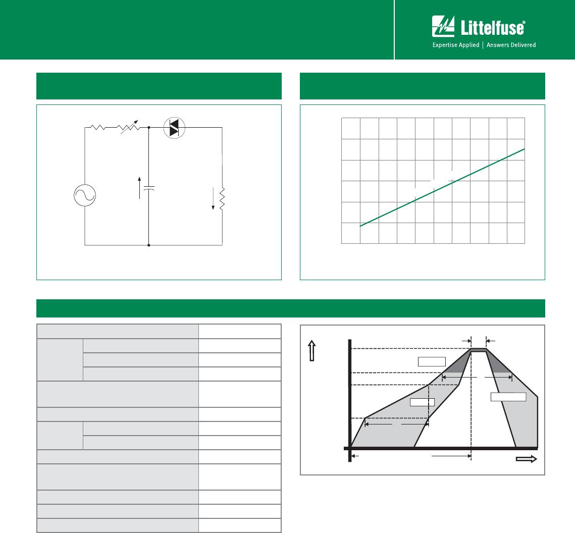
HTxxx & HTMxxx & STxxx Series
Standard Bidirectional DIAC Trigger
DIACs
Physical Specifications
Terminal Finish
100% Matte-Tin Plated/ Pb-Free Solder
Dipped
Body Material
DO-214: UL recognized epoxy meeting
flammabilty classification 94V-0.
DO-35/MINIMELF: Glass case body
Lead Material
DO-214: Copper Alloy
DO-35/MINIMELF: Copper Clad Iron
Reliability/Environmental Tests
Test
Specifications and Conditions
High Temperature
Voltage Blocking
MIL-STD-750, M-1040, Cond A Applied
80% of Rated Min V
BO
(VAC-peak) @
125°C for 1008 hours
Temperature Cycling
MIL-STD-750, M-1051,
100 cycles; -40°C to +150°C;
15-min dwell-time
Temperature/
Humidity
EIA / JEDEC, JESD22-A101
1008 hours; 80% of Rated Min V
BO
(V
DC
):
85°C; 85%
rel humidity
High Temp Storage MIL-STD-750, M-1031,1008 hours; 150°C
Low-Temp Storage 1008 hours; -40°C
Thermal Shock
MIL-STD-750, M-1056
10 cycles; 0°C to 100°C; 5-min dwell
time at each temperature; 10 sec (max)
transfer time between temperature
Autoclave
EIA / JEDEC, JESD22-A102 168 hours
(121°C at 2 ATMs) and 100% R/H
Resistance to
Solder Heat
MIL-STD-750 Method 2031
Solderability ANSI/J-STD-002, category 3, Test A
Lead Bend
MIL-STD-750, M-2036 Cond E
Burn-in 1 firing per 1/2 cycle, 168 hours
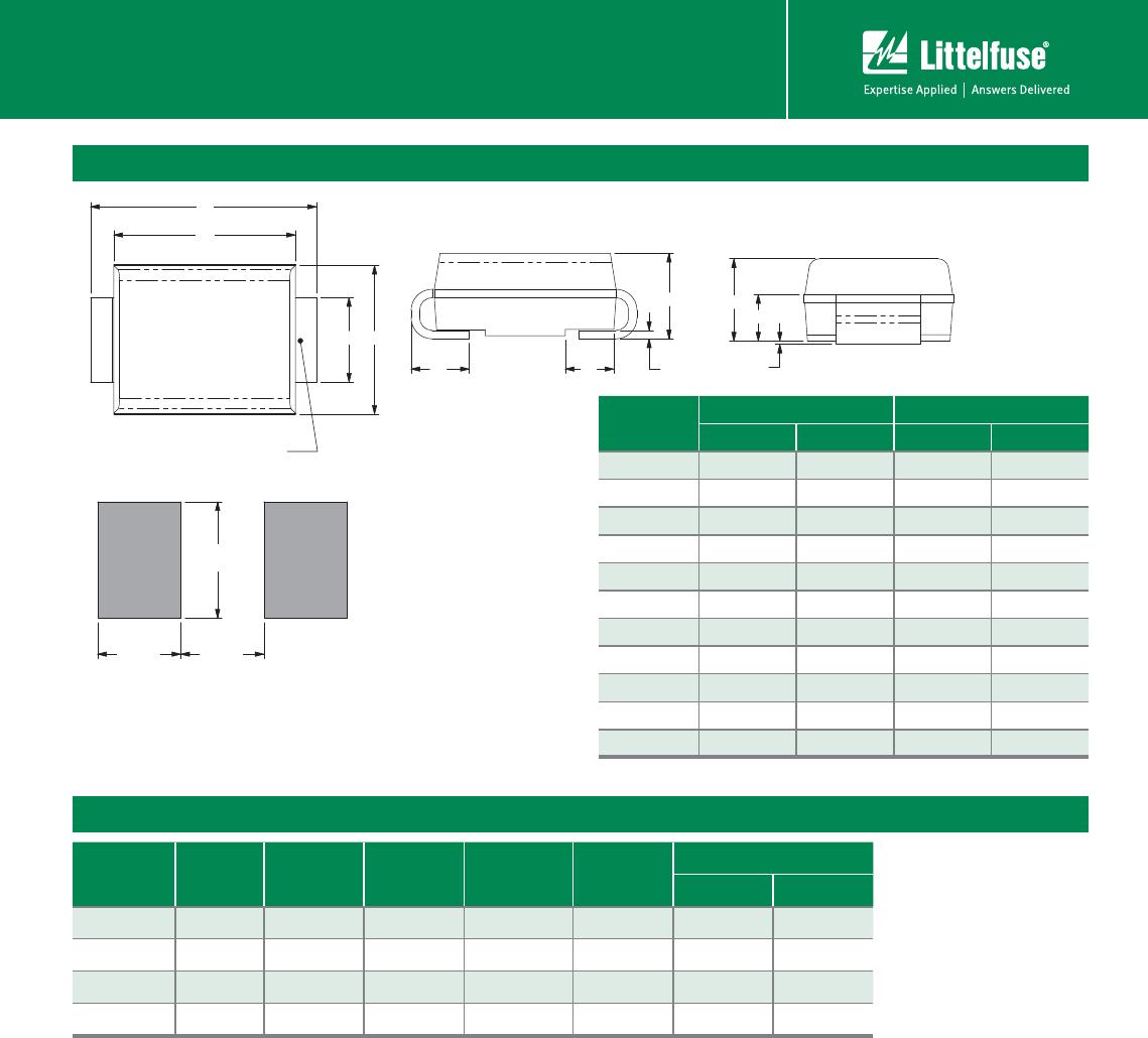
Dimensions – MINIMELF / SOD-80 (MM Package)
A
C
C
D
B
.002 E-F
E
F
Dimensions
Inches Millimeters
Min Typ Max Min Typ Max
A 0.125 0.134 0.142 3.18 3.40 3.61
B 0.066 0.068 0.070 1.68 1.73 1.78
C 0.012 0.018 0.020 0.30 0.46 0.51
D — 0.063 — — 1.60 —
Design Considerations
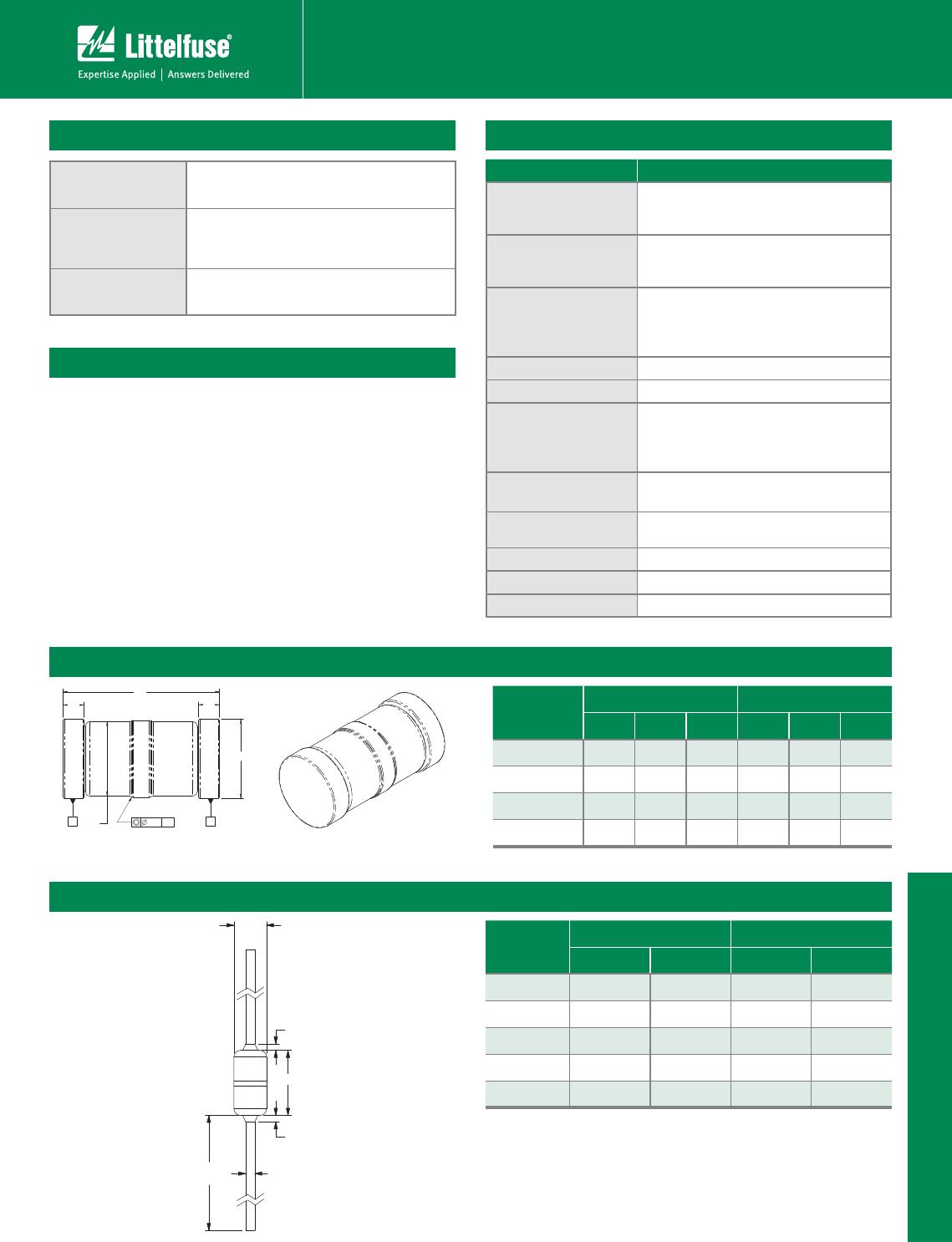
Dimensions – DO-35 (Y Package)
C
B
B
A
E
TYP.
D (TYP.)
Dimension
Inches Millimeters
Min Max Min Max
A (Note 1) 0.060 0.090 1.530 2.280
B
(Note 2) 0.015 0.381
C
(Note 1) 0.135 0.165 3.430 4.190
D 0.018 0.022 0.458 0.558
E 1.000 25.400
Notes:
1. Package contour optional within dimensions A and C. Slugs, if any, shall be included
within this cylinger but shall not be subject to
the minimum limit of Dimention A.
2. Lead diameter is not controlled in this zone to allow for flash, lead finish build-up and
minor irregularities other than slugs.
Careful selection of the correct device for the application’s
operating parameters and environment will go a long
way toward extending the operating life of the Thyristor.
Overheating and surge currents are the main killers of
DIACs. Correct mounting, soldering, and forming of the
leads also help protect against component damage.