BGA2817 All information provided in this document is subject to legal disclaimers. © NXP Semiconductors N.V. 2017. All rights reserved.
Product data sheet Rev. 7 — 30 March 2017 3 of 13
NXP Semiconductors
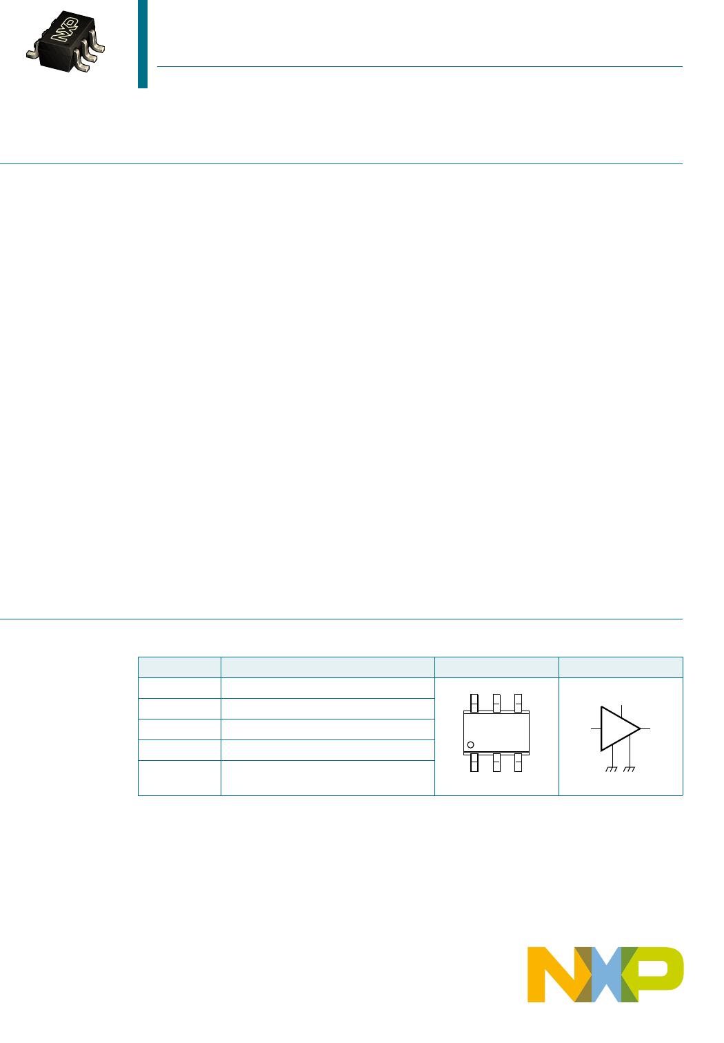
BGA2817
MMIC wideband amplifier
G
p
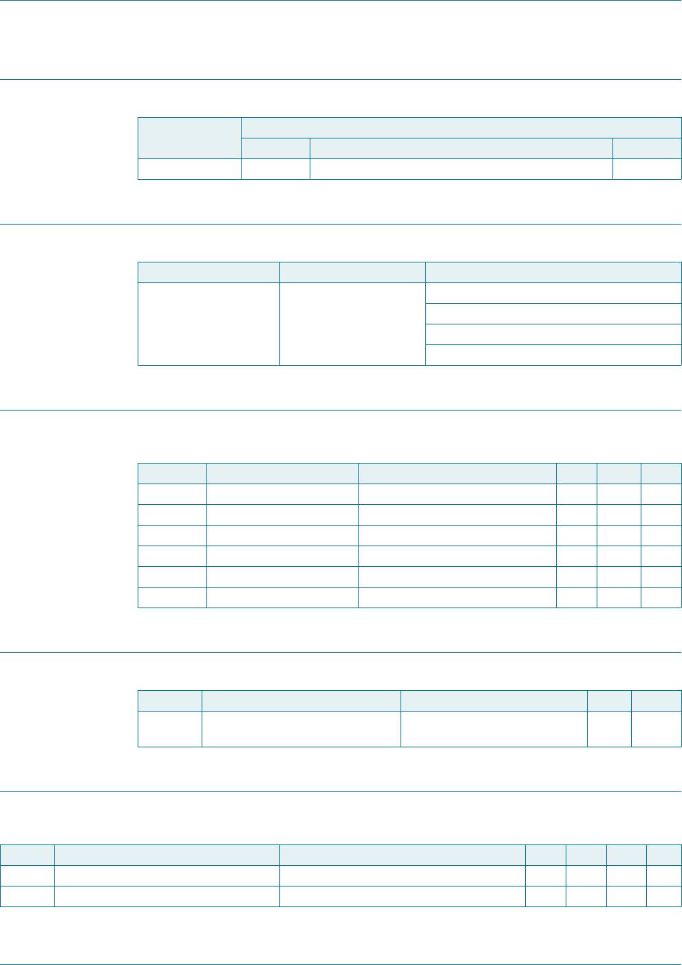
power gain f = 250 MHz 23.6 24.2 24.8 dB
f = 950 MHz 23.5 24.3 25 dB
f = 2150 MHz 23 24.4 25.9 dB
RL
in
input return loss f = 250 MHz 13 15 - dB
f = 950 MHz 1618- dB
f = 2150 MHz 13 20 - dB
RL
out
output return loss f = 250 MHz 12 17 - dB
f = 950 MHz 1617- dB
f = 2150 MHz 17 20 - dB
ISL isolation f = 250 MHz 36 57 - dB
f = 950 MHz 4749- dB
f = 2150 MHz 37 39 - dB
NF noise figure f = 250 MHz - 3.9 4.4 dB
f = 950 MHz - 3.9 4.3 dB
f = 2150 MHz - 3.8 4.2 dB
B
3dB
3 dB bandwidth 3 dB below gain at 1 GHz 3.3 3.5 3.7 GHz
K Rollett stability factor f = 250 MHz 10 21 -
f = 950 MHz 7 9 -
f = 2150 MHz 1.5 2.7 -
P
L(sat)
saturated output power f = 250 MHz 8 8 - dBm
f = 950 MHz 5 7 - dBm
f = 2150 MHz 5 6 - dBm
P
L(1dB)
output power at 1 dB gain compression f = 250 MHz 6 6 - dBm
f = 950 MHz 5 6 - dBm
f = 2150 MHz 4 5 - dBm
IP3
I
input third-order intercept point P
drive
= 40 dBm (for each tone)
f
1
= 250 MHz; f
2
= 251 MHz 9 7- dBm
f
1
= 950 MHz; f
2
= 951 MHz 9 7- dBm
f
1
=2150MHz; f
2
=2151MHz 13 10 - dBm
IP3
O
output third-order intercept point P
drive
= 40 dBm (for each tone)
f
1
= 250 MHz; f
2
=251MHz 1618- dBm
f
1
= 950 MHz; f
2
=951MHz 1618- dBm
f
1
=2150MHz; f
2
= 2151 MHz 12.5 15.5 - dBm
P
L(2H)
second harmonic output power P
drive
= 28 dBm
f
1H
= 250 MHz; f
2H
=500MHz - 53 51 dBm
f
1H
= 950 MHz; f
2H
=1900MHz - 45 41 dBm
IM2 second-order intermodulation distance P
drive
= 31 dBm (for each tone)
f
1
= 250 MHz; f
2
=251MHz 3436- dBc
f
1
= 950 MHz; f
2
=951MHz 3339- dBc
Table 6. Characteristics
…continued
V
CC
= 3.3 V; Z
S
= Z
L
= 50
; P
i
=
40 dBm; T
amb
= 25
C; measured on demo board; unless otherwise specified.
Symbol Parameter Conditions Min Typ Max Unit