BGA2817 All information provided in this document is subject to legal disclaimers. © NXP Semiconductors N.V. 2017. All rights reserved.
Product data sheet Rev. 7 — 30 March 2017 8 of 13
NXP Semiconductors
BGA2817
MMIC wideband amplifier
9. Test information
[1] For decoupling a decoupling capacitor (C
dec
) is used on one of the positions of P5 to P24. The results mentioned in this data sheet have
been obtained using the decoupling capacitor C
dec
on position P22.
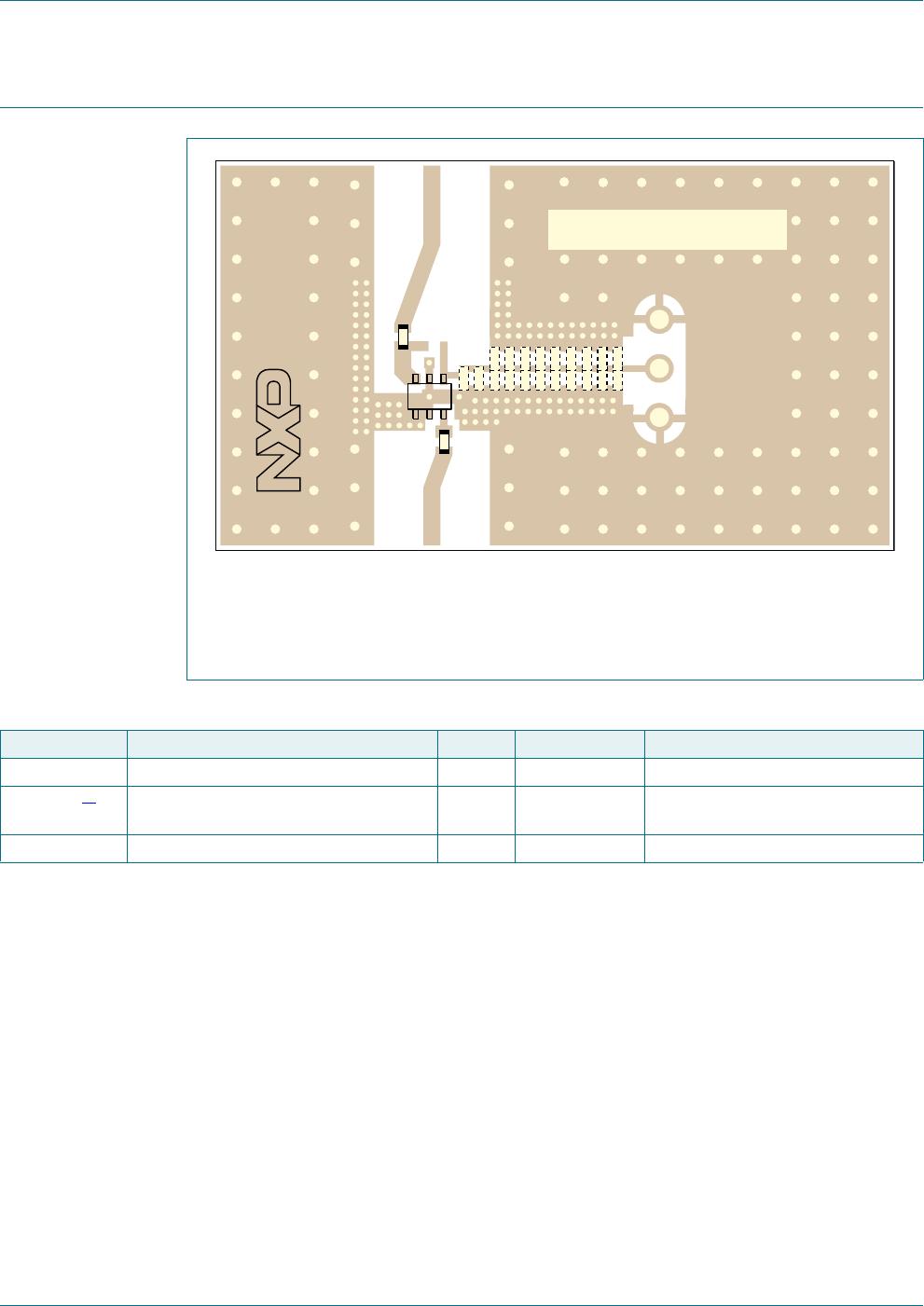
For decoupling a decoupling capacitor (C
dec
) is used on one of the positions of P5 to P24. The
results mentioned in this data sheet have been obtained using the decoupling capacitor C
dec
on
position P22. The distance between the center of pin 1 and the center of position P22 is 7.43 mm.
Fig 4. PCB layout and demo board with components
3
3
3
3
3
3
3
3
3
3
3
5),1 5)287
3
3
3
3
3
3
3
3
3
*1'
9
&&
*1'
&
&
6(0,&21'8&7256
%*$[[[627(9%
Table 15. List of components used for the typical application
Component Description Value Dimensions Remarks
C1, C2 multilayer ceramic chip capacitor 470 pF 0603 X7R RF coupling capacitor
P5 to P24
[1]
position for multilayer ceramic chip
capacitor C
dec
470 pF 0603 X7R RF decoupling capacitor
IC1 BGA2817 MMIC - SOT363