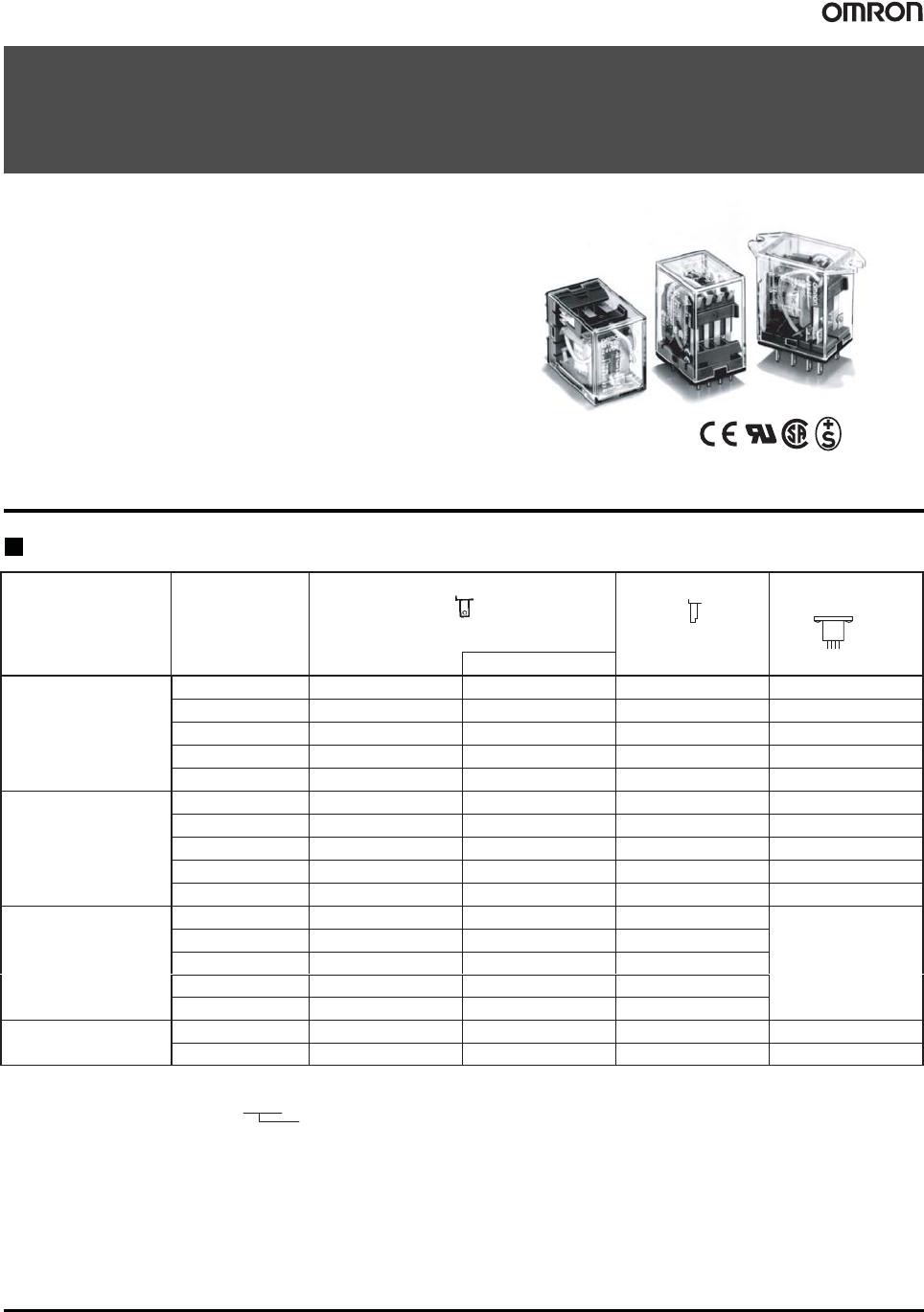
1
General-purpose Relay
MY
An Improved Miniature Power Relay with
Many Models for Sequence Control and
Power Applications
 A wide range of relay variations including ones with operation
indicators, built-in diodes, etc.
 Arc barrier standard on 3- and 4-pole Relays.
 Dielectric strength: 2,000 VAC.
LR
Ordering Information
List of Models
Type Contact form
Plug-in socket/solder terminals
PCB terminals
Upper-mounting/
solder terminals
W
ith indicator
Standard
DPDT MY2 MY2N MY2-02 MY2F
DPDT (bifurcated)
MY2Z MY2ZN MY2Z-02 MY2ZF
3PDT MY3 MY3N MY3-02 MY3F
4PDT MY4 MY4N MY4-02 MY4F
4PDT (bifurcated)
MY4Z MY4ZN MY4Z-02 MY4ZF
W
ith built-in diode
DPDT MY2-D MY2N-D2 ––– –––
(DC only)
DPDT (bifurcated)
MY2Z-D MY2ZN-D2 ––– –––
3PDT MY3-D MY3N-D2 ––– –––
4PDT MY4-D MY4N-D2 ––– –––
4PDT (bifurcated)
MY4Z-D MY4ZN-D2 ––– –––
With built-in CR DPDT MY2-CR MY2N-CR –––
Not available.
(AC only)
DPDT (bifurcated)
MY2Z-CR ––– –––
3PDT MY3-CR ––– –––
4PDT MY4-CR MY4N-CR –––
4PDT (bifurcated)
MY4Z-CR ––– –––
W
ith test button
DPDT MY2I4 MY2I4N ––– –––
4PDT MY4I4 MY4I4N ––– –––
Rated coil voltage
Note: 1.
When ordering, add the rated coil voltage to the model number
. Rated coil voltages are given in the coil ratings table.
Example: MY2, 6 V
AC
2.
The standard contacts for MY2Z-series Relays and for the MY4Z are gold-plated.
MY
MY
2
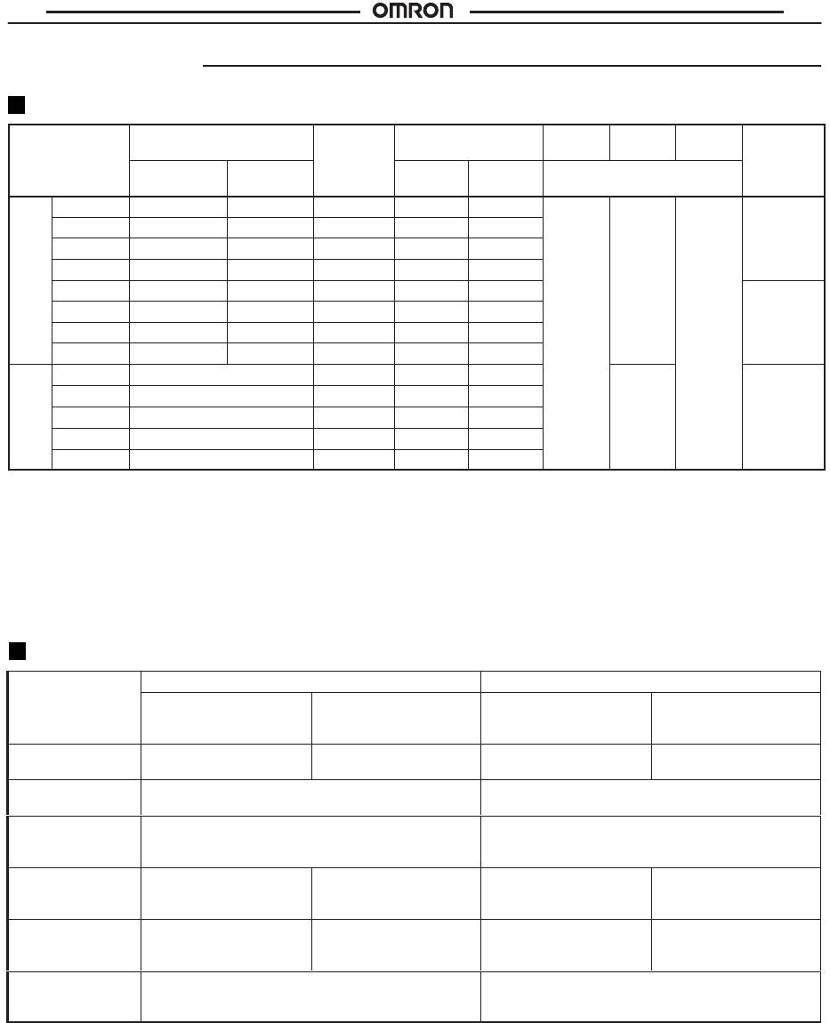
Accessories (Order Separately)
Sockets
Poles Front-mounting
socket
Back-mounting socket
(DIN-rail/screw mounting)
Solder terminals
W
ire-wrap terminals
PCB
W/ clip
W/o clip
W/ clip
W/o clip
terminals
2
PYF08A
PYF08A-E (finger protection)
PYF08A-N (finger protection)
PY08 PY08-Y1 PY08QN PY08QN-Y1 PY08–02
3 PYF1
1A
PY11 PY11-Y1 PY11QN PY11QN-Y1 PY11-02
4
PYF14A
PYF14A-N (finger protection)
PYF14A-E (finger protection)
PY14
PY14-3*
PY14-Y1 PY14QN PY14QN-Y1 PY14-02
Note: *1.
Equipped with operation check terminal.
2.
The PYF08A(-E), PYF1
1A, and PYF14A(-E) have been approved as individual sockets by UL S08 and CSA C22.2.
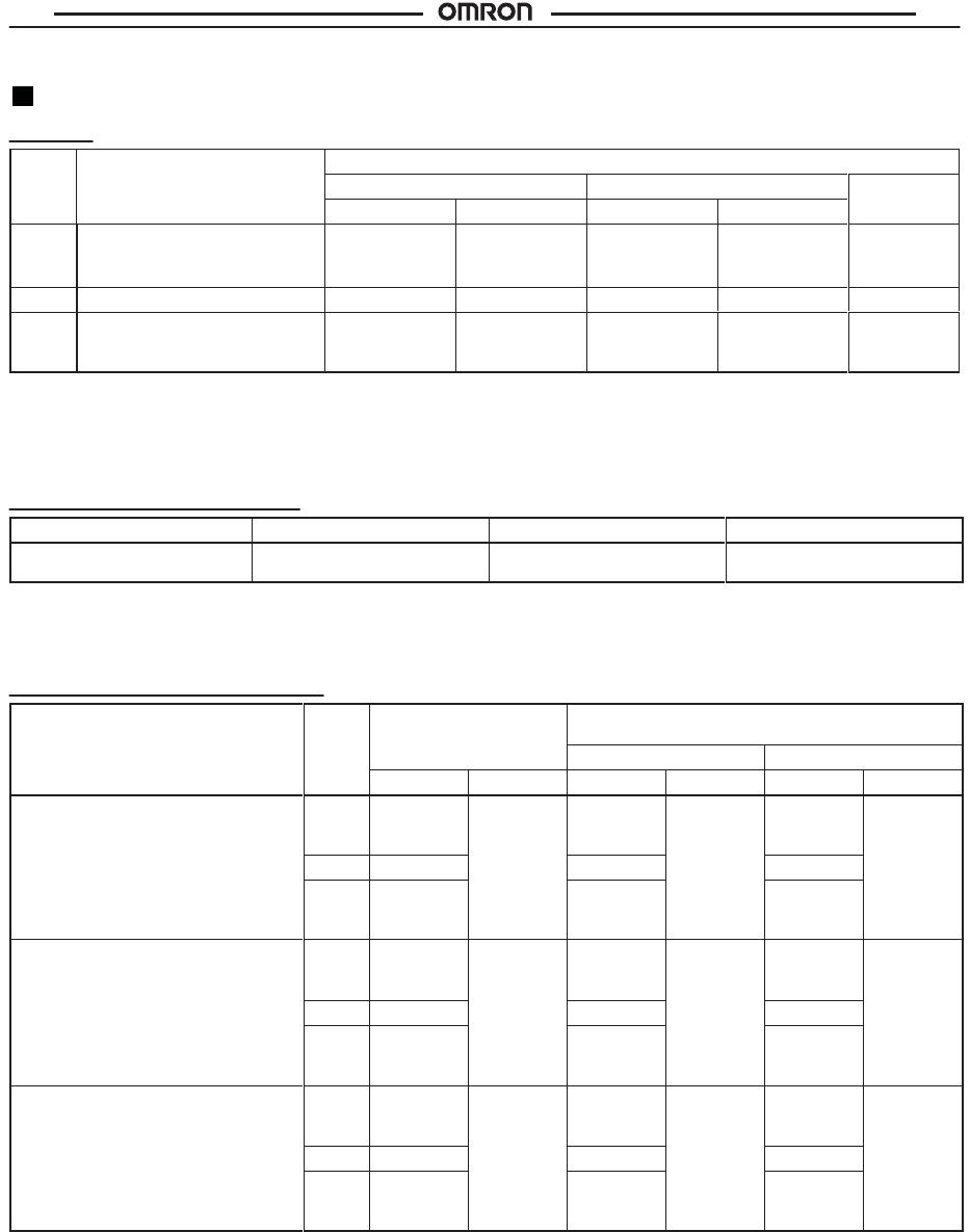
Mounting Plates for Sockets
Socket
model For 1 socket
For 18 sockets For 36 sockets
PY08, PY1
1, PY14, PY08QN(2),
PY11QN(2), PY14QN(2)
PYP-1 PYP-18 PYP-36
Note:
PYP-18 and PYP-36 can be cut into any desired length in accordance with the number of sockets.
Socket Hold-down Clip Pairing
Relay
type
Poles Front-connecting
sockets
Back-connecting sockets
(rail-/screw-mounted)
Solder/wire-wrap
terminals
PCB
terminals
Socket Clip Socket Clip Socket Clip
Standard, bifurcated contacts, operation
indicator,
built-in diode.
2
PYF08A-N,
PYF08A-E,
PYF08A
PYC-A1 PY08(QN) PYC-P PY08(QN) PYC-P
3 PYF11A PY11(QN) PY11(QN)
4 PYF14A-N,
PYF14A-E,
PYF14A
PY14(QN) PY14(QN)
T
est button
2
PYF08A-N,
PYF08A-E,
PYF08A
PYC-A1 PY08(QN) PYC-P2 PY08(QN) PYC-P2
3 PYF11A PY11(QN) PY11(QN)
4 PYF14A-N,
PYF14A-E,
PYF14A
PY14(QN) PY14(QN)
CR circuit
2
PYF08A-N,
PYF08A-E,
PYF08A
Y92H-3 PY08(QN) PYC-1 PY08(QN) PYC-1
3 PYF11A PY11(QN) PY11(QN)
4 PYF14A-N,
PYF14A-E,
PYF14A
PY14(QN) PY14(QN)
MY
MY
3
Specifications
Coil Ratings
Rated
voltage
Rated current
Coil
resistance
Inductance
(reference value)
Must
operate
Must
release
Max.
voltage
Power
consum.
(A )
50 Hz 60 Hz
es sta ce
Arm.
OFF
Arm. ON
% of rated voltage
co su
(Approx.)
AC
6 V
214.1 mA
183 mA
12.2
:
0.04 H 0.08 H
80% 30% 110%
1.0 to
12V
A
12 V
106.5 mA
91 mA
46
:
0.17 H 0.33 H
max. min.
1.2 V
A
(60 Hz)
24 V
53.8 mA
46 mA
180
:
0.69 H 1.30 H
(60 H
z
)
50 V
25.7 mA
22 mA
788
:
3.22 H 5.66 H
100/1
10 V
1
1.7/12.9 mA
10/1
1 mA
3,750
:
14.54 H
24.6 H
0.9 to
11V
A
1
10/120 V 9.9/10.8 mA 8.4/9.2 mA
4,430
:
19.20 H
32.1 H
1.1 V
A
(60 Hz)
200/220 V
6.2/6.8 mA 5.3/5.8 mA
12,950
:
54.75 H 94.07 H
(60 H
z
)
220/240 V
4.8/5.3 mA 4.2/4.6 mA
18,790
:
83.50 H
136.40 H
DC
6 V
150 mA
40
:
0.17 H 0.33 H
10%
0.9 W
12 V
75 mA
160
:
0.73 H 1.37 H
min.
24 V
36.9 mA
650
:
3.20 H 5.72 H
48 V
18.5 mA
2,600
:
10.60 H 21.00 H
100/1
10 V
9.1/10 mA
1
1,000
:
45.60 H 86.20 H
Note: 1. The
rated current and coil resistance are measured at a coil temperature of 23
q
C with tolerances
of +15%/–20% for rated currents
and r
15% for DC coil resistance.
2.
Performance characteristic data are measured at a coil temperatures of 23
qC.
3.
AC coil resistance and impedance are provided as reference values (at 60 Hz).
4. Power
consumption drop was measured for the above data. When
driving transistors, check leakage current and connect a bleeder
resistor
if required.
Contact Ratings
Item
Double- or three-pole
Four-pole
Resistive load
(cosf
= 1)
Inductive load
(cosf
=0.4,
L/R=7 ms)
Inductive load
(cosf
=0.4,
L/R=7 ms)
Rated load
5 A, 220 V
AC
5 A, 24 VDC
2 A, 220 V
AC
2 A, 24 VDC
3 A, 220 V
AC
3 A, 24 VDC
0.8 A, 220 V
1.5 A, 24 VDC
Carry
current
5 A 3 A
Max.
switching
voltage
250 VAC
125 VDC
250 V
AC
125 VDC
Max.
switching
current
5 A 5 A 3 A 3 A
Max.
switching
capacity
1,100 VA
120 W
440 VA
48 W
660 VA
72 W
176 VA
36 W
Min.
permissible
load*
Standard type: 100 mA, 5 VDC
Bifurcated type: 100
P
A, 1 VDC
Standard type: 1
mA, 1 VDC
Bifurcated type: 100
PA, 1 VDC
*Note:
P level:
O
60
= 0.1 x 10
-6
/operation, reference value
Resistive load
(cosf
= 1)

MY4-02 AC12

Mfr. #:
Manufacturer:
Omron Automation and Safety
Description:
General Purpose Relays GP Relay
Lifecycle:
New from this manufacturer.
Delivery:
DHL FedEx Ups TNT EMS
Payment:
T/T Paypal Visa MoneyGram Western Union