GS9064-CKDE3

GENNUM CORPORATION P.O. Box 489, Stn. A, Burlington, Ontario, Canada L7R 3Y3
Tel. +1 (905) 632-2996 Fax. +1 (905) 632-5946 E-mail: info@gennum.com
www.gennum.com
Revision Date: June 2006 Document No. 22212 - 3
DATA SHEET
GS9064
KEY FEATURES
SMPTE 259 and SMPTE 344 compliant
automatic cable equalization
supports DVB-ASI at 270Mb/s
typical maximum equalized length of Belden 1694A
cable at 270Mb/s is 350m
•50Ω differential output (with internal 50Ω pull-ups)
cable length indicator
output mute based on maximum cable length adjust or
manual override
Pb-free and Green
single 3.3V power supply operation
operating temperature range: 0°C to +70°C
pin compatible with HDLINX
II GS1524 multirate SDI
adaptive cable equalizer
APPLICATIONS
SMPTE 259M Coaxial Cable Serial Digital Interfaces
DESCRIPTION
The GS9064 is a second-generation high-speed bipolar
integrated circuit designed to equalize and restore signals
received over 75Ω co-axial cable at data rates from
143Mb/s up to 540Mb/s. The GS9064 is designed to
support SMPTE 344M and SMPTE 259M and is optimized
for performance at 270Mb/s.
The GS9064 features DC restoration to compensate for the
DC content of SMPTE pathological test patterns, and
incorporates a Cable Length Indicator (CLI) that provides a
linear indication of the amount of cable being equalized.
A voltage programmable mute threshold (MCLADJ) is
included to allow muting of the GS9064 output when a
selected cable length is reached. This feature allows the
GS9064 to distinguish between low amplitude SDI signals
and noise at the input of the device. The CD
/MUTE pin
provides an indication of the GS9064 mute status in
addition to functioning as a mute control input. The output
of the GS9064 may be forced to an active or a mute
condition by applying a voltage to the CD
/MUTE pin.
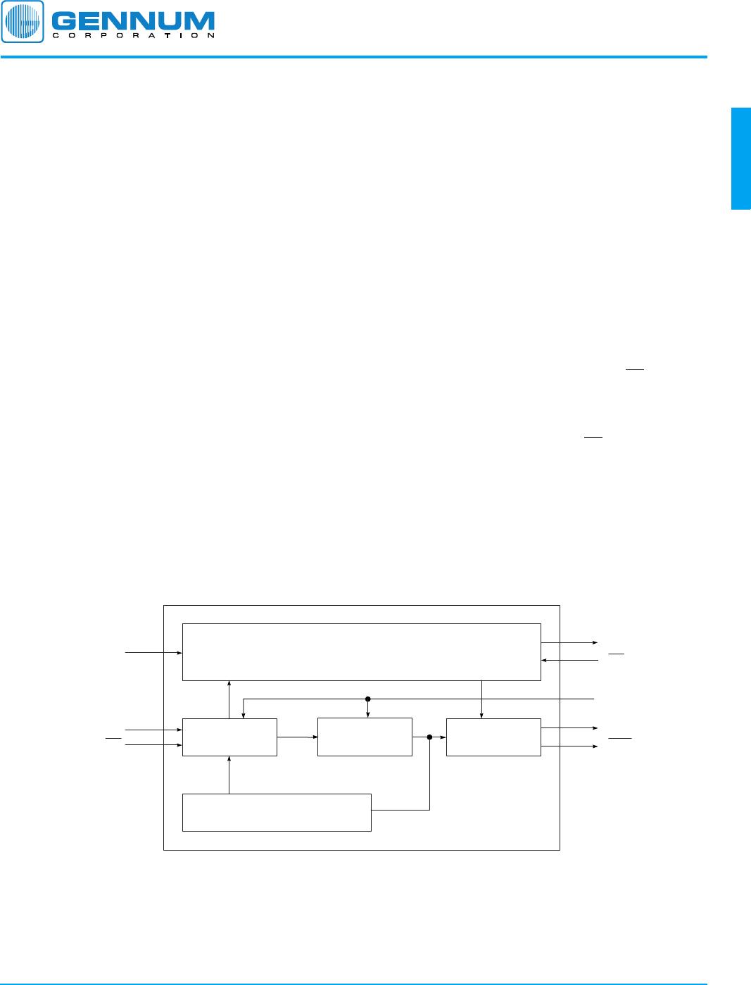
GS9064 FUNCTIONAL BLOCK DIAGRAM
CABLE LENGTH INDICATOR/ADJUSTOR
CARRIER DETECT
MUTE
EQUALIZER DC RESTORE OUTPUT
AGC
CLI
CD/MUTE
SDO
SDOSDI
SDI
MCLADJ
BYPASS
GS9064 SD SDI
Adaptive Cable Equalizer
GENNUM CORPORATION 22212 - 3
2 of 12
GS9064
TABLE OF CONTENTS
1. PIN OUT .......................................................................................................................................... 3
1.1 PIN ASSIGNMENT................................................................................................................ 3
1.2 PIN DESCRIPTIONS .............................................................................................................. 3
2. ELECTRICAL CHARACTERISTICS .......................................................................................................... 4
2.1 ABSOLUTE MAXIMUM RATINGS .................................................................................................................... 4
2.2 DC ELECTRICAL CHARACTERISTICS........................................................................................ 4
2.3 AC ELECTRICAL CHARACTERISTICS........................................................................................ 5
2.4 SOLDER REFLOW PROFILE.................................................................................................... 6
2.5 INPUT/OUTPUT CIRCUITS .................................................................................................... 7
2.6 TYPICAL PERFORMANCE CURVES.......................................................................................... 8
3. DETAILED DESCRIPTION..................................................................................................................... 9
3.1 SERIAL DIGITAL INPUT ......................................................................................................... 9
3.2 AUTOMATIC CABLE EQUALIZATION........................................................................................ 9
3.3 CABLE LENGTH INDICATION & CARRIER DETECT/MUTE ........................................................... 9
4. APPLICATION REFERENCE DESIGN .................................................................................................... 10
4.1 PCB LAYOUT .................................................................................................................... 10
4.2 TYPICAL APPLICATION CIRCUIT ........................................................................................... 10
5. REFERENCES.................................................................................................................................. 10
6. PACKAGE & ORDERING INFORMATION............................................................................................... 11
6.1 PACKAGE DIMENSIONS...................................................................................................... 11
6.2 ORDERING INFORMATION................................................................................................... 11
7. REVISION HISTORY .......................................................................................................................... 12
GENNUM CORPORATION 22212 - 3
3 of 12
GS9064
1. PIN OUT
1.1 PIN ASSIGNMENT
1.2 PIN DESCRIPTIONS
PIN
NUMBER NAME TYPE DESCRIPTION
1 CLI Output CABLE LENGTH INDICATOR
An analog voltage proportional to the cable length connected to the serial digital input.
NOTE: CLI is recommended for data rates up to 360 Mb/s only.
2, 15 V
CC
Input
Power
Most positive power supply connection. Connect to +3.3V.
3, 6, 11,
14
V
EE
Input
Power
Most negative power supply connection. Connect to ground.
4, 5 SDI, SDI
Input Serial digital differential inputs.
7, 8 AGC+, AGC- Passive
Input
External AGC capacitor. Should be set to 1µF.
9 BYPASS Input Forces the CORE stage and the DC RESTORE stage into bypass mode when HIGH. No
equalization occurs in this mode.
10 MCLADJ Input MAXIMUM CABLE LENGTH ADJUST
Adjusts the approximate maximum amount of cable to be equalized (from 0m to the
maximum cable length). The output is muted (latched to the last state) when the
maximum cable length is achieved.
NOTE: MCLADJ is recommended for data rates up to 360 Mb/s only.
12, 13 SDO
, SDO Output Equalized serial digital differential outputs.
16 CD
/MUTE Input /
Output
MUTE INDICATOR-CONTROL / CARRIER DETECT
OUTPUT: the output voltage drops to below 1.2V when the carrier is present and the
data outputs are active.
INPUT: if the CD
/MUTE pin is tied to ground, the data output will never mute and the
MCLADJ setting is overwritten. If the CD
/MUTE pin is tied to VCC, the data outputs will
always mute and the MCLADJ setting is overwritten.
CLI
V
CC
V
EE
SDI
SDI
V
EE
AGC+
AGC-
CD/MUTE
V
CC
V
EE
SDO
SDO
V
EE
MCLADJ
BYPASS
GS9064
16PIN SOIC
TOP VIEW
1
2
3
4
5
6
7
8
16
15
14
13
12
11
10
9

GS9064-CKDE3

Mfr. #:
Manufacturer:
Semtech
Description:
Equalizers SOIC-16N (50/tube)
Lifecycle:
New from this manufacturer.
Delivery:
DHL FedEx Ups TNT EMS
Payment:
T/T Paypal Visa MoneyGram Western Union

Products related to this Datasheet