Features
•High speed signal transmission(25Mbps NRZ Signal)
• High PD sensitivity optimized for red light
• Data : NRZ signal
• Low power consumption for extended battery life
• Built-in threshold control for improved noise Margin
• The product itself will remain within RoHS compliant version
• Receiver sensitivity: up to –27dBm (Min. for 25Mbps)
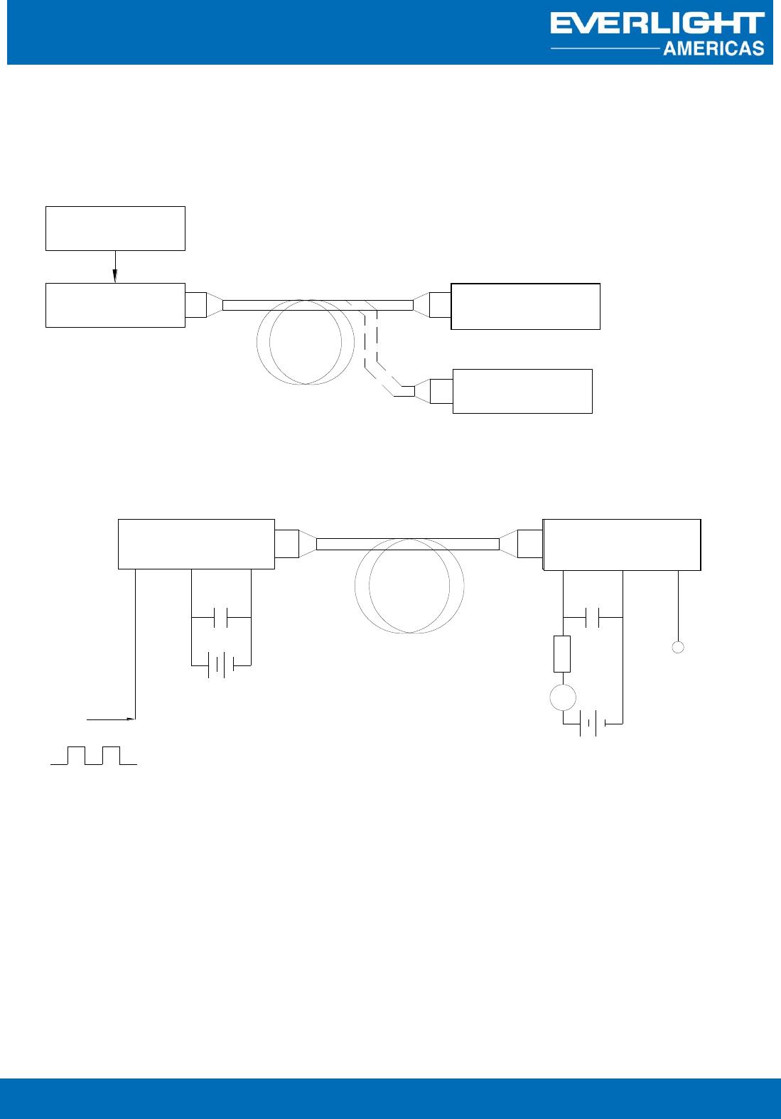
Description
The optical receiver is packaged with custom optic data link interface, integrated
on a proprietary CMOS PDIC process.
The unit functions by converting optical signals into electric ones.
The unit is operated at 3.0 ~ 5.5 V and the signal output interface is TTL
compatible with high performance at low power consumption.
Applications
• Digital Optical Data-Link
• Dolby AC-3 Digital Audio Interface
• HDMI Digital (192kHz) Audio Interface