I
NTEGRATED
C
IRCUITS
D
IVISION
e
3
Pb
DS-IX2127-R03 www.ixysic.com 1
Driver Characteristics
Features
Floating Channel Designed for Bootstrap Operation
up to 600V
Tolerant to Negative Transient Voltages; dV/dt
Immune
Undervoltage Lockout
3.3V, 5V, and 12V Input Logic Compatible
Open-Drain FAULT
Indicator Pin Shows
Over-Current Shutdown
Output in Phase with the Input
Applications
High-Speed Gate Driver
Motor Drive Inverter
Description
The IX2127 is a high-voltage, high-speed power
MOSFET and IGBT driver. High-voltage level-shift
circuitry enables this device to operate up to 600V.
IXYS Integrated Circuits Division’s proprietary
common-mode design techniques provide stable
operation in high dV/dt noise environments.
An on-board comparator can be used to detect an
over-current condition in the driven MOSFET or IGBT
device, and then shut down drive to that device. An
open-drain output, FAULT
, indicates that an
over-current shutdown has occurred.
The gate driver output typically can source 250mA
and sink 500mA, which is suitable for fluorescent lamp
ballast, motor control, SMPS, and other converter
drive topologies.
The IX2127 is provided in 8-pin DIP and 8-pin SOIC
packages, and is available in Tape & Reel versions.
See ordering information below.
Ordering Information
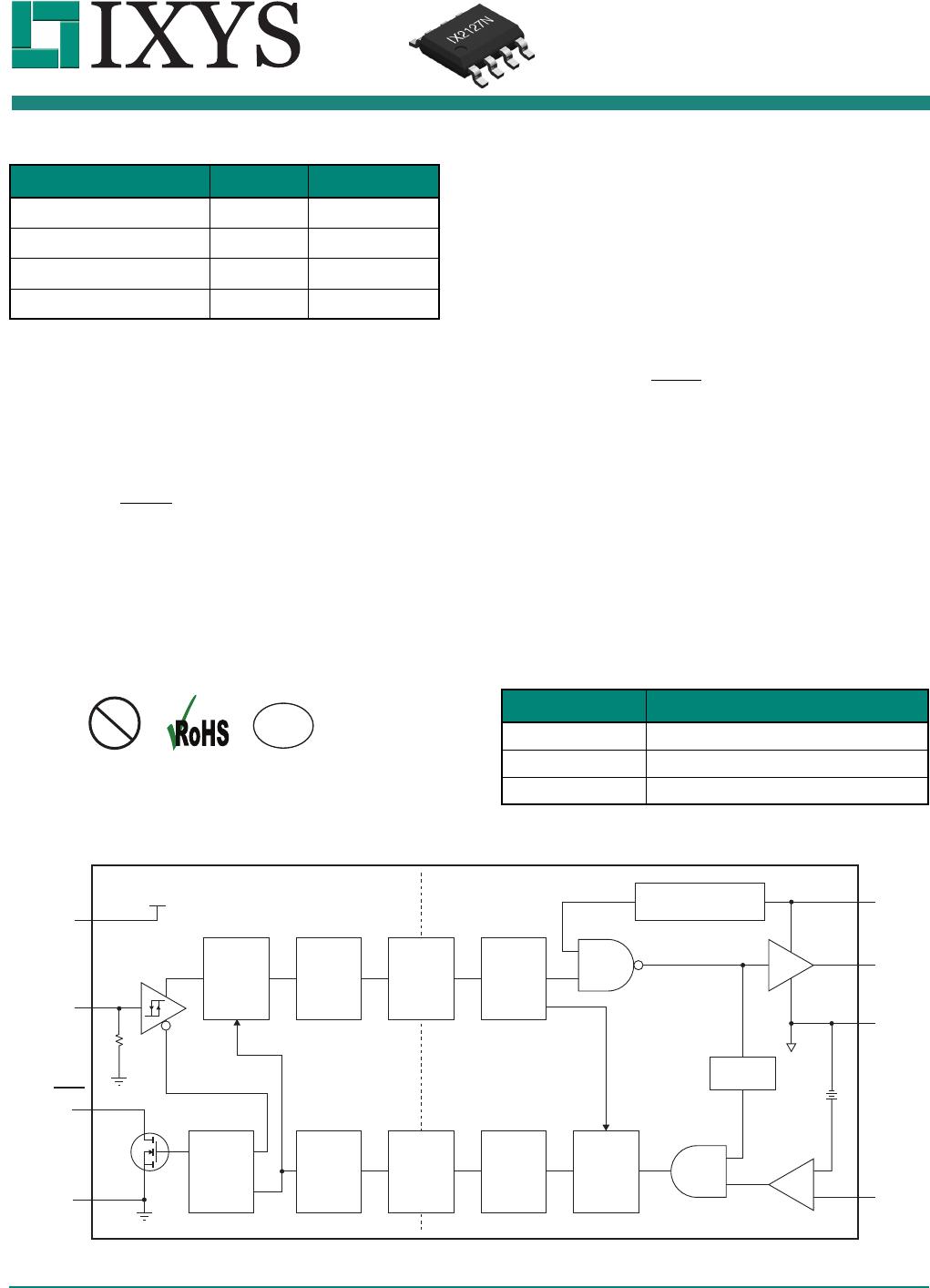
IX2127 Block Diagram
Parameter Rating Units
V
OFFSET
600 V
I
O +/-
(Source/Sink)
250/500 mA
V
CSth
250 mV
t
ON
/ t
OFF
(Typical)
100 ns
Part Description
IX2127G 8-Pin DIP (50/Tube)
IX2127N 8-Pin SOIC (100/Tube)
IX2127NTR 8-Pin SOIC (2000/Reel)
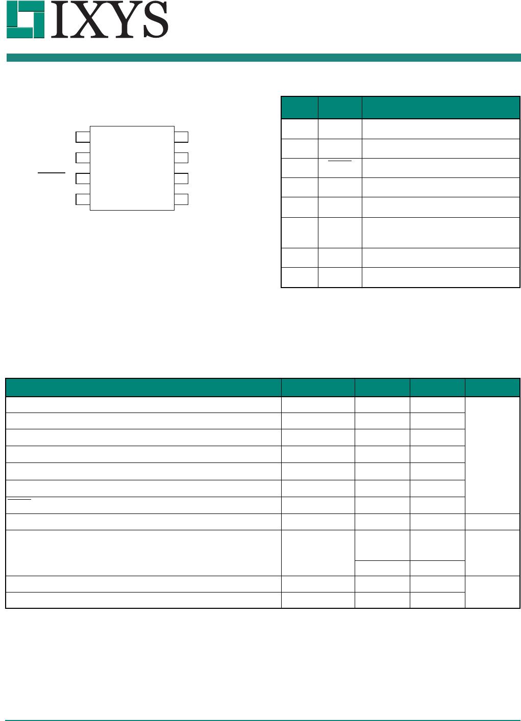
V
CC
IN
FAULT
COM
V
B
HO
V
S
CS
Buffer
Comparator
Delay
Undervoltage Lockout
Data LatchTransmitter
High-Low
Level Shift
Low-High
Level Shift
ReceiverTransmitterData Latch
Receiver
Low Side High Side
QR
S
Enable
Enable
Blanking
Signal
+
_
V
CC
IX2127
High-Voltage
Power MOSFET & IGBT Driver
I
NTEGRATED
C
IRCUITS
D
IVISION
IX2127
2 www.ixysic.com R03
1. Specifications . . . . . . . . . . . . . . . . . . . . . . . . . . . . . . . . . . . . . . . . . . . . . . . . . . . . . . . . . . . . . . . . . . . . . . . . . . . . . . . . . . . . . . . . . . . . . . 3
1.1 Package Pinout . . . . . . . . . . . . . . . . . . . . . . . . . . . . . . . . . . . . . . . . . . . . . . . . . . . . . . . . . . . . . . . . . . . . . . . . . . . . . . . . . . . . . . . . . 3
1.2 Pin Description. . . . . . . . . . . . . . . . . . . . . . . . . . . . . . . . . . . . . . . . . . . . . . . . . . . . . . . . . . . . . . . . . . . . . . . . . . . . . . . . . . . . . . . . . . 3
1.3 Absolute Maximum Ratings . . . . . . . . . . . . . . . . . . . . . . . . . . . . . . . . . . . . . . . . . . . . . . . . . . . . . . . . . . . . . . . . . . . . . . . . . . . . . . . . 3
1.4 Recommended Operating Conditions . . . . . . . . . . . . . . . . . . . . . . . . . . . . . . . . . . . . . . . . . . . . . . . . . . . . . . . . . . . . . . . . . . . . . . . . 4
1.5 General Conditions . . . . . . . . . . . . . . . . . . . . . . . . . . . . . . . . . . . . . . . . . . . . . . . . . . . . . . . . . . . . . . . . . . . . . . . . . . . . . . . . . . . . . . 4
1.6 Electrical Characteristics . . . . . . . . . . . . . . . . . . . . . . . . . . . . . . . . . . . . . . . . . . . . . . . . . . . . . . . . . . . . . . . . . . . . . . . . . . . . . . . . . . 5
1.7 Timing Characteristics . . . . . . . . . . . . . . . . . . . . . . . . . . . . . . . . . . . . . . . . . . . . . . . . . . . . . . . . . . . . . . . . . . . . . . . . . . . . . . . . . . . . 6
2. Performance Data . . . . . . . . . . . . . . . . . . . . . . . . . . . . . . . . . . . . . . . . . . . . . . . . . . . . . . . . . . . . . . . . . . . . . . . . . . . . . . . . . . . . . . . . . . . 8
3. Manufacturing Information . . . . . . . . . . . . . . . . . . . . . . . . . . . . . . . . . . . . . . . . . . . . . . . . . . . . . . . . . . . . . . . . . . . . . . . . . . . . . . . . . . . 11
3.1 Moisture Sensitivity . . . . . . . . . . . . . . . . . . . . . . . . . . . . . . . . . . . . . . . . . . . . . . . . . . . . . . . . . . . . . . . . . . . . . . . . . . . . . . . . . . . . . 11
3.2 ESD Sensitivity . . . . . . . . . . . . . . . . . . . . . . . . . . . . . . . . . . . . . . . . . . . . . . . . . . . . . . . . . . . . . . . . . . . . . . . . . . . . . . . . . . . . . . . . 11
3.3 Reflow Profile. . . . . . . . . . . . . . . . . . . . . . . . . . . . . . . . . . . . . . . . . . . . . . . . . . . . . . . . . . . . . . . . . . . . . . . . . . . . . . . . . . . . . . . . . . 11
3.4 Board Wash . . . . . . . . . . . . . . . . . . . . . . . . . . . . . . . . . . . . . . . . . . . . . . . . . . . . . . . . . . . . . . . . . . . . . . . . . . . . . . . . . . . . . . . . . . . 11
3.5 Mechanical Dimensions. . . . . . . . . . . . . . . . . . . . . . . . . . . . . . . . . . . . . . . . . . . . . . . . . . . . . . . . . . . . . . . . . . . . . . . . . . . . . . . . . . 12
I
NTEGRATED
C
IRCUITS
D
IVISION
IX2127
R03 www.ixysic.com 3
1 Specifications
1.1 Package Pinout
1.2 Pin Description
1.3 Absolute Maximum Ratings
Unless otherwise specified, ratings are provided at T
A
=25°C and all bias levels are with respect to COM.
Absolute maximum electrical ratings are at 25°C
Absolute maximum ratings are stress ratings. Stresses in
excess of these ratings can cause permanent damage to
the device. Functional operation of the device at conditions
beyond those indicated in the operational sections of this
data sheet is not implied.
1
2
3
4
5
6
7
8
V
CC
IN
COM
FAULT
V
B
HO
V
S
CS
Pin# Name Description
1
V
CC
Logic Supply Voltage
2IN
Logic Input
3FAULT
Fault Indicator Output
4COM
Logic Ground
5
V
S
High Side Return
6CS
Comparator Input,
Over-Current Detect
7HO
High Side Gate Drive Output
8
V
B
High Side Supply Voltage
Parameter Symbol Minimum Maximum Units
Logic Supply Voltage
V
CC
-0.3 15
V
High Side Floating Supply Voltage
V
B
-0.3 625
High Side Floating Offset Voltage
V
S
V
B
-12 V
B
+0.3
Logic Input Voltage
V
IN
-0.3
V
CC
+0.3
High Side Floating Output Voltage
V
HO
V
S
-0.3 V
B
+0.3
Current Sense Voltage
V
CS
V
S
-0.3 V
B
+0.3
FAULT Output Voltage
V
FLT
-0.3
V
CC
+0.3
Allowable Offset Supply Voltage Transient
dV
S
/dt
-50V/ns
Package Power Dissipation
8-Lead DIP
P
D
-1
W
8-Lead SOIC
- 0.625
Junction Temperature
T
J
-150
°C
Storage Temperature
T
S
-55 150

IX2127G

Mfr. #:
Manufacturer:
IXYS Integrated Circuits
Description:
Gate Drivers High-Voltage MOSFET 600V, 250/500mA
Lifecycle:
New from this manufacturer.
Delivery:
DHL FedEx Ups TNT EMS
Payment:
T/T Paypal Visa MoneyGram Western Union

Products related to this Datasheet