MKP385
www.vishay.com
Vishay BCcomponents
Revision: 03-Jun-15
10
Document Number: 28174
For technical questions, contact: dc-film@vishay.com
THIS DOCUMENT IS SUBJECT TO CHANGE WITHOUT NOTICE. THE PRODUCTS DESCRIBED HEREIN AND THIS DOCUMENT
ARE SUBJECT TO SPECIFIC DISCLAIMERS, SET FORTH AT www.vishay.com/doc?91000
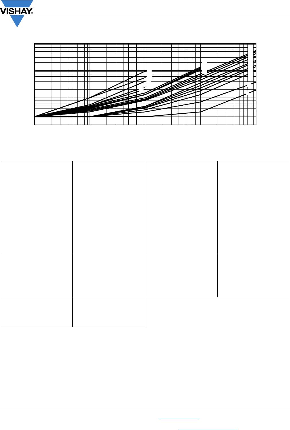
Tangent of loss angle as a function of frequency (typical curve)
160 V:
C 0.018 µF, curve 1
0.018 < C 0.12 µF, curve 2
0.12 < C 0.16 µF, curve 5
0.16 < C 0.33 µF, curve 6
0.33 < C 0.47 µF, curve 7
0.47 < C 0.91 µF, curve 10
0.91 < C 1.1 µF, curve 11
1.1 < C 1.6 µF, curve 12
1.6 < C 2.4 µF, curve 13
2.4 < C 3 µF, curve 14
3 < C 5.6 µF, curve 15
5.6 < C 43 µF, curve 18
43 < C 82 µF, curve 20
250 V:
C 0.043 µF, curve 2
0.043 < C 0.091 µF, curve 3
0.091 < C 0.11 µF, curve 5
0.11 < C 0.43 µF, curve 6
0.33 < C 0.47 µF, curve 7
0.43 < C 0.91 µF, curve 10
0.91 < C 3.3 µF, curve 12
3.3 < C 5.6 µF, curve 13
5.6 < C 33 µF, curve 18
33 < C 62 µF, curve 20
400 V:
C 0.010 µF, curve 1
0.010 < C 0.036 µF, curve 2
0.036 < C 0.043 µF, curve 3
0.043 < C 0.18 µF, curve 4
0.18 < C 0.43 µF, curve 8
0.43 < C 0.75 µF, curve 10
0.75 < C 3.0 µF, curve 11
3.3 < C 15 µF, curve 17
15 < C
27 µF, curve 19
630 V:
C 0.018 µF, curve 1
0.018 < C 0.024 µF, curve 2
0.024 < C 0.043 µF, curve 3
0.043 < C 0.11 µF, curve 4
0.11 < C 0.24 µF, curve 7
0.24 < C 2.4 µF, curve 9
2.4 < C 8.2 µF, curve 16
8.2 < C 15 µF, curve 19
850 V:
C 0.0091 µF, curve 1
0.0091 < C 0.051 µF, curve 2
0.051 < C 0.12 µF, curve 3
0.12 < C 0.68 µF, curve 4
0.68 < C 1.3 µF, curve 6
1000 V:
C 0.015 µF, curve 1
0.015 < C 0.056 µF, curve 2
0.056 < C 0.10 µF, curve 3
0.1 < C 0.91 µF, curve 4
1250 V:
C 0.033 µF, curve 1
0.033 < C 0.091 µF, curve 2
0.091 < C 0.68 µF, curve 3
1600 V:
C 0.0091 µF, curve 1
0.0091 < C 0.27 µF, curve 2
0.27 < C 0.36 µF, curve 3
0.36 < C 1 µF, curve 5
2000 V:
C 0.018 µF, curve1
0.018 < C 0.22 µF, curve 2
0.22 < C 1 µF, curve 4
2500 V:
C 0.082 µF, curve1
0.082 < C
0.39 µF, curve 2
0.39 < C 0.68 µF, curve 4
1
10
100
1000
100 1000 10 000 100 000 1 000 000
Dissipation factor (x 10
-4
)
f (Hz)
20
19
18
17
16
15
14
13
12
11
10
9
8
7
6
5
4
3
2
1
MKP385
www.vishay.com
Vishay BCcomponents
Revision: 03-Jun-15
11
Document Number: 28174
For technical questions, contact: dc-film@vishay.com
THIS DOCUMENT IS SUBJECT TO CHANGE WITHOUT NOTICE. THE PRODUCTS DESCRIBED HEREIN AND THIS DOCUMENT
ARE SUBJECT TO SPECIFIC DISCLAIMERS, SET FORTH AT www.vishay.com/doc?91000
POWER DISSIPATION AND MAXIMUM COMPONENT TEMPERATURE RISE
The power dissipation must be limited in order not to exceed the maximum allowed component temperature rise as a function
of the free air ambient temperature.
The power dissipation can be calculated according type detail specification “HQN-384-01/101: Technical information film
capacitors with the typical tgd of the curves.”.
The component temperature rise (T) can be measured (see section “Measuring the component temperature” for more details)
or calculated by T = P/G:
T = component temperature rise (°C)
P = power dissipation of the component (mW)
G = heat conductivity of the component (mW/°C)
MEASURING THE COMPONENT TEMPERATURE
A thermocouple must be attached to the capacitor body as in:
The temperature is measured in unloaded (T
amb
) and maximum loaded condition (T
C
).
The temperature rise is given by T = T
C
- T
amb
.
To avoid radiation or convection, the capacitor should be tested in a wind-free box.
HEAT CONDUCTIVITY (G) AS A FUNCTION OF (ORIGINAL) PITCH AND CAPACITOR BODY
THICKNESS IN mW/°C
W
max
(mm)
HEAT CONDUCTIVITY (mW/°C)
PITCH
5 mm
PITCH
7.5 mm
PITCH
10 mm
PITCH
15 mm
PITCH
22.5 mm
PITCH
27.5 mm
PITCH
37.5 mm
PITCH
52.5 mm
3-4------
3.53-------
4 - 5 6.5 - - - - -
4.54-------
5-67.510----
6 5.5 7 9 11 19 - - -
7 - - - 12 21 - - -
8.5 - - - 16 25 - - -
9- - - - - 31 - -
10---1828---
11 - - - - - 36 - -
12 - - - - 34 - - -
13 - - - - - 42 - -
14.5 - - - - - - - -
15 - - - - - 48 - -
18 - - - - - 57 - -
18.5 - - - - - - 89 -
21 - - - - - 68 - -
21.5 - - - - - - 102 -
24 - - - - - - 116 -
25 - - - - - - - 152
30 - - - - - - 134 181
35 - - - - - - - 197
Thermocouple
CBA758
MKP385
www.vishay.com
Vishay BCcomponents
Revision: 03-Jun-15
12
Document Number: 28174
For technical questions, contact: dc-film@vishay.com
THIS DOCUMENT IS SUBJECT TO CHANGE WITHOUT NOTICE. THE PRODUCTS DESCRIBED HEREIN AND THIS DOCUMENT
ARE SUBJECT TO SPECIFIC DISCLAIMERS, SET FORTH AT www.vishay.com/doc?91000
APPLICATION NOTE AND LIMITING CONDITIONS
For capacitors connected in parallel, normally the proof voltage and possibly the rated voltage must be reduced. For information
depending of the capacitance value and the number of parallel connections contact: dc-film@vishay.com
These capacitors are not suitable for mains applications as across-the-line capacitors without additional protection, as
described hereunder. These mains applications are strictly regulated in safety standards and therefore electromagnetic
interference suppression capacitors conforming the standards must be used.
To select the capacitor for a certain application, the following conditions must be checked:
1. The peak voltage (U
p
) shall not be greater than the rated DC voltage (U
RDC
)
2. The peak-to-peak voltage (U
p-p
) shall not be greater thanthe maximum (U
p-p
) to avoid the ionization inception level
3. The voltage peak slope (dU/dt) shall not exceed the rated voltage pulse slope in an RC-circuit at rated voltage and without
ringing. If the pulse voltage is lower than the rated DC voltage, the rated voltage pulse slope may be multiplied by U
RDC
and
divided by the applied voltage.
For all other pulses following equation must be fulfilled:
T is the pulse duration
4. The maximum component surface temperature rise must be lower than the limits (see graph “Max. allowed component
temperature rise”).
5. Since in circuits used at voltages over 280 V peak-to-peak the risk for an intrinsically active flammability after a capacitor
breakdown (short circuit) increases, it is recommended that the power to the component is limited to 100 times the values
mentioned in the table: “Heat Conductivity”
6. When using these capacitors as across-the-line capacitor in the input filter for mains applications or as series connected
with an impedance to the mains the applicant must guarantee that the following conditions are fulfilled in any case (spikes
and surge voltages from the mains included).
EXAMPLE
C = 4n7 - 1600 V used for the voltage signal shown in next drawing.
U
p-p
= 1000 V; U
p
= 900 V; T
1
= 12 µs; T
2
= 64 µs; T
3
= 4 µs
The ambient temperature is 80 °C. In case of failure, the oscillation is blocked.
Checking the conditions:
1. The peak voltage U
p
= 900 V is lower than 1600 V
DC
2. The peak-to-peak voltage 1000 V is lower than 22 x 550 V
AC
= 1600 U
p-p
3. The voltage pulse slope (dU/dt) = 1000 V/4 µs = 250 V/µs
This is lower than 4000 V/µs (see specific reference data for each version)
4. The dissipated power is 35 mW as calculated with fourier terms and typical tgd.
The temperature rise for Wmax. = 6 mm and pitch = 15 mm will be 35 mW/9 mW/°C = 3.9 °C
This is lower than 10 °C temperature rise at 80 °C, according graph.
5. Oscillation is blocked
6. Not applicable
VOLTAGE SIGNAL
VOLTAGE CONDITIONS FOR 6 ABOVE
ALLOWED VOLTAGES T
amb
≤ 85 °C 85 °C < T
amb
≤ 110 °C 110 °C < T
amb
≤ 125 °C
Maximum continuous RMS voltage U
RAC
0.7 x U
RAC
0.5 x U
RAC
Maximum temporary RMS-over voltage (< 24 h) 1.25 x U
RAC
0.875 x U
RAC
0.625 x U
RAC
Maximum peak voltage (V
o-p
) (< 2 s) 1.6 x U
RDC
1.1 x U
RDC
0.8 x U
RDC
2
dU
dt
--------


2
0
T
dt U
RDC
dU
dt
--------


rated
Voltage
U
p
T
3
T
1
T
2
U
p-p
Time

MKP385215250JI02W0

Mfr. #:
Manufacturer:
Description:
Film Capacitors MKP385 0,0015 F 5% 2500Vdc Pitch22,5
Lifecycle:
New from this manufacturer.
Delivery:
DHL FedEx Ups TNT EMS
Payment:
T/T Paypal Visa MoneyGram Western Union