Page 5
(1) Control voltage 18-52 VAC/VDC is available upon request.
(2) All parameters at 25°C unless otherwise specified.
(3) “P” option output will self trigger between 900-1200 Vpk, not suitable for capacitive loads.
(4) High inductive loads requires nominal control voltage; AC input models only.
(5) Increase minimum voltage by 1 V for operations from -20 to -40°C.
(6) Turn-on time for Instantaneous turn-on versions is 0.1 msec.
(7) No freezing or condensation allowed.
(8) When protected with the appropriate class and rated fuse. For detailed info please contact Crydom Technical Support.
(9) For single surge pulse Tc=25°C; Tj=125°C. For AC Output SSRs, AC RMS value of surge current equals the peak value divided by √2 (1.414).
(10) UL approved rating is the one that intersects at 40°C.
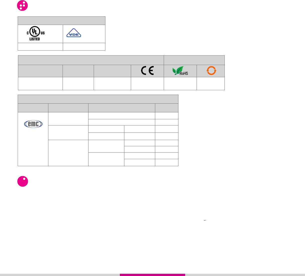
GENERAL NOTES
Electromagnetic Compatibility
Generic
Standard
Immunity Tests Test Specification Level
Electrostatic Discharge
IEC 61000-4-2
Fast transients (burst)
IEC 61000-4-4
Surge
IEC 61000-4-5
8kV air discharge
6kV contact discharge
Output 2kV, 5kHz, 100kHz
Input 1kV, 5kHz, 100kHz
1kV Line to Line
2kV Line to Earth
AC Input Option
Output
Performance
Criterion A
Criterion A
Criterion B
Criterion B
Criterion B
Criterion B
1kV Line to Line
2kV Line to Earth
Criterion A
Criterion A
IEC 61000-6-2
Immunity for
Industrial
Environments
Approvals (Tested and Certified according To)
UL 508 and C22.2 No. 14
E116949
EN 62314
REG-Nr. xxxxxx
Conformances Environmental
Designed in
accordance with
IEC 60950-1 IEC 60335-1, Section 30 Directive 2006/95/EC Directive 2011/65/EU GBT 26572-2011
Resistances to heat
and fire
50
Vibration and Shock
Resistance
IEC 61373: Category 1,
Class B
AGENCY APPROVALS, CONFORMANCES, ENVIRONMENTAL AND EMC
www.sensata.com
Copyright © 2017 Sensata Technologies Inc.
Sensata Technologies, Inc. (“Sensata”) data sheets are solely intended to assist designers (“Buyers”) who are developing systems that
incorporate Sensata products (also referred to herein as “components”). Buyer understands and agrees that Buyer remains responsible
for using its independent analysis, evaluation and judgment in designing Buyer’s systems and products. Sensata data sheets have been
created using standard laboratory conditions and engineering practices. Sensata has not conducted any testing other than that
specifically described in the published documentation for a particular data sheet. Sensata may make corrections, enhancements,
improvements and other changes to its data sheets or components without notice.
Buyers are authorized to use Sensata data sheets with the Sensata component(s) identified in each particular data sheet. HOWEVER, NO
OTHER LICENSE, EXPRESS OR IMPLIED, BY ESTOPPEL OR OTHERWISE TO ANY OTHER SENSATA INTELLECTUAL PROPERTY RIGHT,
AND NO LICENSE TO ANY THIRD PARTY TECHNOLOGY OR INTELLECTUAL PROPERTY RIGHT, IS GRANTED HEREIN. SENSATA DATA
SHEETS ARE PROVIDED “AS IS”. SENSATA MAKES NO WARRANTIES OR REPRESENTATIONS WITH REGARD TO THE DATA SHEETS
OR USE OF THE DATA SHEETS, EXPRESS, IMPLIED OR STATUTORY, INCLUDING ACCURACY OR COMPLETENESS. SENSATA
DISCLAIMS ANY WARRANTY OF TITLE AND ANY IMPLIED WARRANTIES OF MERCHANTABILITY, FITNESS FOR A PARTICULAR
PURPOSE, QUIET ENJOYMENT, QUIET POSSESSION, AND NON-INFRINGEMENT OF ANY THIRD PARTY INTELLECTUAL PROPERTY
RIGHTS WITH REGARD TO SENSATA DATA SHEETS OR USE THEREOF.
All products are sold subject to Sensata’s terms and conditions of sale supplied at www.sensata.com SENSATA ASSUMES NO
LIABILITY FOR APPLICATIONS ASSISTANCE OR THE DESIGN OF BUYERS’ PRODUCTS. BUYER ACKNOWLEDGES AND AGREES THAT IT
IS SOLELY RESPONSIBLE FOR COMPLIANCE WITH ALL LEGAL, REGULATORY AND SAFETY-RELATED REQUIREMENTS CONCERNING ITS
PRODUCTS, AND ANY USE OF SENSATA COMPONENTS IN ITS APPLICATIONS, NOTWITHSTANDING ANY APPLICATIONS-RELATED
INFORMATION OR SUPPORT THAT MAY BE PROVIDED BY SENSATA.
Mailing Address: Sensata Technologies, Inc., 529 Pleasant Street, Attleboro, MA 02703, USA.
CONTACT US
Americas
+1 (877) 502 5500 – Option 2
sales.crydom@sensata.com
Europe, Middle East & Africa
+44 (1202) 416170
ssr-info.eu@sensata.com
Asia Pacific
sales.isasia@list.sensata.com
China +86 (21) 2306 1500
Japan +81 (45) 277 7117
Korea +82 (31) 601 2004
India +91 (80) 67920890
Rest of Asia +886 (2) 27602006
ext 2808
Rev. 011618 ECN 20312 FDE-07-01 Rev. B