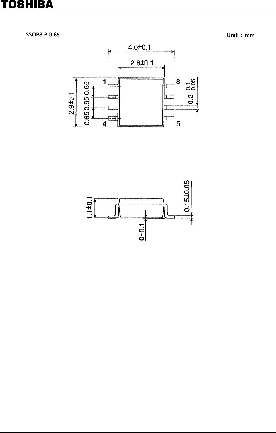
TC7WH04FU/FK
2009-09-25
4
AC Characteristics
(unless otherwise specified, Input: t
r
= t
f
= 3 ns)
Test Condition Ta = 25°C Ta = −40 to 85°C
Characteristics Symbol
V
CC
(V) C
L
(pF) Min Typ. Max Min Max
Unit
15 ⎯ 5.0 7.1 1.0 8.5
3.3 ± 0.3
50 ⎯ 7.5 10.6 1.0 12.0
15 ⎯ 3.8 5.5 1.0 6.5
Propagation delay time
t
pLH
t
pHL
⎯
5.0 ± 0.5
50 ⎯ 5.3 7.5 1.0 8.5
ns
Input capacitance C
IN
⎯ ⎯ 4 10 ⎯ 10 pF
Power dissipation capacitance C
PD
(Note2) ⎯ 18 ⎯ ⎯ ⎯ pF
Note 2: C
PD
is defined as the value of the internal equivalent capacitance which is calculated from the operating
current consumption without load.
Average operating current can be obtained by the equation:
I
CC (opr)
= C
PD
・V
CC
・f
IN
+ I
CC
/3
Noise Characteristics
(Ta
=
25°C, input: t
r
=
t
f
=
3 ns)
Characteristics Symbol Test Condition
V
CC
(V)
Typ. Limit Unit
Quiet output maximum dynamic V
OL
V
OLP
C
L
= 50 pF 5.0 0.3 0.8 V
Quiet output minimum dynamic V
OL
V
OLV
C
L
= 50 pF 5.0 −0.3 −0.8 V
Minimum high level dynamic V
IH
V
IHD
C
L
= 50 pF 5.0 ⎯ 3.5 V
Maximum low level dynamic V
IH
V
ILD
C
L
= 50 pF 5.0 ⎯ 1.5 V
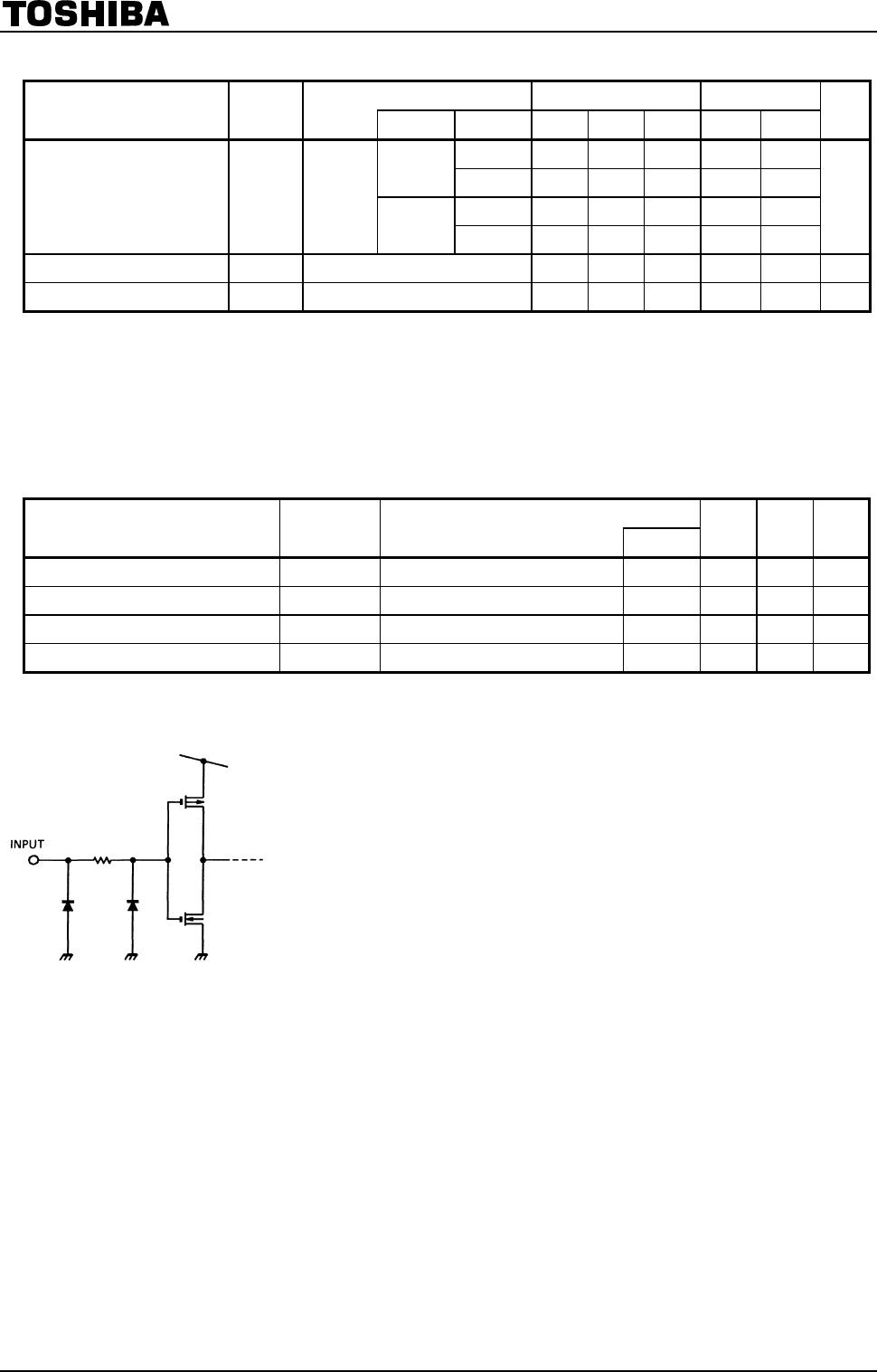
Input Equivalent Circuit