13©2017 Integrated Device Technology, Inc. November 9, 2017
8S89831I Datasheet
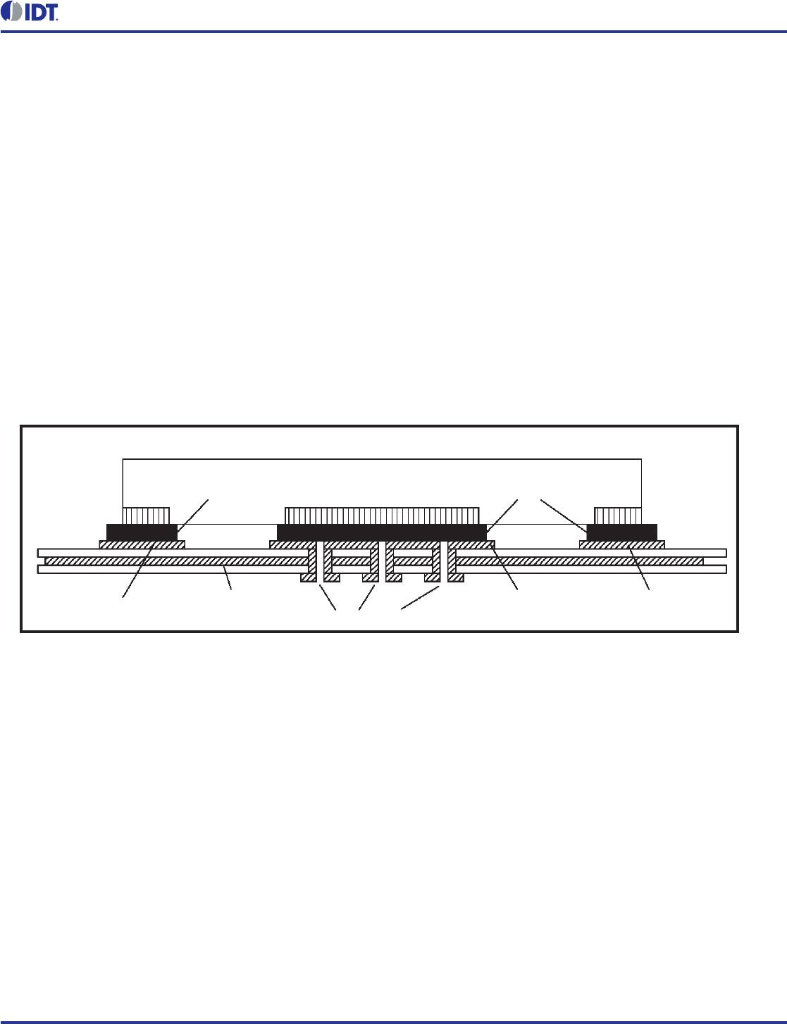
VFQFN EPAD Thermal Release Path
In order to maximize both the removal of heat from the package and
the electrical performance, a land pattern must be incorporated on
the Printed Circuit Board (PCB) within the footprint of the package
corresponding to the exposed metal pad or exposed heat slug on the
package, as shown in Figure 6. The solderable area on the PCB, as
defined by the solder mask, should be at least the same size/shape
as the exposed pad/slug area on the package to maximize the
thermal/electrical performance. Sufficient clearance should be
designed on the PCB between the outer edges of the land pattern
and the inner edges of pad pattern for the leads to avoid any shorts.
While the land pattern on the PCB provides a means of heat transfer
and electrical grounding from the package to the board through a
solder joint, thermal vias are necessary to effectively conduct from
the surface of the PCB to the ground plane(s). The land pattern must
be connected to ground through these vias. The vias act as “heat
pipes”. The number of vias (i.e. “heat pipes”) are application specific
and dependent upon the package power dissipation as well as
electrical conductivity requirements. Thus, thermal and electrical
analysis and/or testing are recommended to determine the minimum
number needed. Maximum thermal and electrical performance is
achieved when an array of vias is incorporated in the land pattern. It
is recommended to use as many vias connected to ground as
possible. It is also recommended that the via diameter should be 12
to 13mils (0.30 to 0.33mm) with 1oz copper via barrel plating. This is
desirable to avoid any solder wicking inside the via during the
soldering process which may result in voids in solder between the
exposed pad/slug and the thermal land. Precautions should be taken
to eliminate any solder voids between the exposed heat slug and the
land pattern. Note: These recommendations are to be used as a
guideline only. For further information, please refer to the Application
Note on the Surface Mount Assembly of Amkor’s Thermally/
Electrically Enhance Leadframe Base Package, Amkor Technology.
Figure 6. P.C. Assembly for Exposed Pad Thermal Release Path – Side View (drawing not to scale)
SOLDERSOLDER
PINPIN EXPOSED HEAT SLUG
PIN PAD PIN PADGROUND PLANE LAND PATTERN
(GROUND PAD)
THERMAL VIA
14©2017 Integrated Device Technology, Inc. November 9, 2017
8S89831I Datasheet
Schematic Example
Figure 7 shows a schematic example of the 8S89831I. This
schematic provides examples of input and output handling. The
8S89831I input has built-in 50 termination resistors. The input can
directly accept various types of differential signal without AC couple.
For AC couple termination, the 8S89831I also provides the
VREF_AC pin for proper offset level after the AC couple. This
example shows the 8S89831I input driven by a 2.5V LVPECL driver
with AC couple. The 8S89831I outputs are LVPECL driver. In this
example, we assume the traces are long transmission line and the
receiver is high input impedance without built-in matched load. An
example of 3.3V LVPECL termination is shown in this schematic.
Additional termination approaches are shown in the LVPECL
Termination Application Note.
Figure 7. 8S89831I Application Schematic Example
3.3V
3.3V
C7
0.1u
R5
133
R4
82.5
Zo = 50
R7
133
R3
133
R6
82.5
Zo = 50
+
-
R9
133
LVPECL
Zo = 50
+
-
C1
0.1u
C6
R1
100
Zo = 50
Zo = 50
R8
82.5
Zo = 50
U1
ICS8S89831i
Q1
1
nQ1
2
Q2
3
nQ2
4
Q3
5
nQ3
6
VCC
7
EN
8
nIN
9
VREF_AC
10
VT
11
IN
12
VEE
13
VCC
14
Q0
15
nQ0
16
C5
R2
100
C2
0.1u
R10
82.5
2.5V
3.3V
3.3V
3.3V
3.3V
15©2017 Integrated Device Technology, Inc. November 9, 2017
8S89831I Datasheet
Power Considerations
This section provides information on power dissipation and junction temperature for the 8S89831I.
Equations and example calculations are also provided.
1. Power Dissipation.
The total power dissipation for the 8S89831I is the sum of the core power plus the power dissipation in the load(s).
The following is the power dissipation for V
CC
= 3.3V + 5% = 3.465V, which gives worst case results.
Note: Please refer to Section 3 for details on calculating power dissipation in the load.
Power (core)
MAX
= V
CC_MAX
* I
EE_MAX
= 3.465V * 45mA = 155.925mW
Power (outputs)
MAX
= 32.94mW/Loaded Output pair
If all outputs are loaded, the total power is 4 * 32.94mW = 131.76mW
Power Dissipation for internal termination R
T
Power (R
T
)
MAX
= (V
IN_MAX
)
2
/ R
T_MIN
= (1.2V)
2
/ 80 = 18mW
Total Power_
MAX
(3.3V, with all outputs switching) = 155.925mW + 131.76mW + 18mW = 305.685mW
2. Junction Temperature.
Junction temperature, Tj, is the temperature at the junction of the bond wire and bond pad, and directly affects the reliability of the device. The
maximum recommended junction temperature is 125°C. Limiting the internal transistor junction temperature, Tj, to 125°C ensures that the bond
wire and bond pad temperature remains below 125°C.
The equation for Tj is as follows: Tj =
JA
* Pd_total + T
A
Tj = Junction Temperature
JA
= Junction-to-Ambient Thermal Resistance
Pd_total = Total Device Power Dissipation (example calculation is in section 1 above)
T
A
= Ambient Temperature
In order to calculate junction temperature, the appropriate junction-to-ambient thermal resistance
JA
must be used. Assuming no air flow and
a multi-layer board, the appropriate value is 74.7°C/W per Table 6 below.
Therefore, Tj for an ambient temperature of 85°C with all outputs switching is:
85°C + 0.306W * 74.7°C/W = 107.9°C. This is well below the limit of 125°C.
This calculation is only an example. Tj will obviously vary depending on the number of loaded outputs, supply voltage, air flow and the type of
board (multi-layer).
Table 6. Thermal Resistance
JA
for 16 Lead VFQFN, Forced Convection
Thermal Parameters by Velocity
Meters per Second 012.5
JA
74.7°C/W 65.3°C/W 58.5°C/W
JB
5.7°C/W - -
JC
59.7°C/W - -

8S89831AKILF

Mfr. #:
Manufacturer:
IDT
Description:
Clock Buffer 1:4 Differential to LVEPCL/ECO Fanout Bu
Lifecycle:
New from this manufacturer.
Delivery:
DHL FedEx Ups TNT EMS
Payment:
T/T Paypal Visa MoneyGram Western Union

Products related to this Datasheet