Panasonic Corporation 2013©
Panasonic Corporation Automation Controls Buisiness Division
industrial.panasonic.com/ac/e/
Notes on Using Narrow pitch Connectors
–
10–
ACCTB48E 201303-T
Regarding soldering
1. Reflow soldering
1) Measure the recommended profile
temperature for reflow soldering by
placing a sensor on the PC board near
the connector surface or terminals. (The
setting for the sensor will differ depending
on the sensor used, so be sure to
carefully read the instructions that comes
with it.)
2) As for cream solder printing, screen
printing is recommended.
3) To determine the relationship between
the screen opening area and the PC-
board foot pattern area, refer to the
diagrams in the recommended patterns
for PC boards and metal masks. Make
sure to use the terminal tip as a reference
position when setting. Avoid an excessive
amount of solder from being applied,
otherwise, interference by the solder will
cause an imperfect contact.
4) Consult us when using a screen-
printing thickness other than that
recommended.
5) When mounting on both sides of the
PC board and the connector is mounting
on the underside, use adhesives or other
means to ensure the connector is
properly fixed to the PC board. (Double
reflow soldering on the same side is
possible.)
6) N
2 reflow, conducting reflow soldering
in a nitrogen atmosphere, increases the
solder flow too greatly, enabling wicking
to occur. Make sure that the solder feed
rate and temperature profile are
appropriate.
Soldering conditions
Please use the reflow temperature profile
conditions recommended below for
reflow soldering. Please contact us
before using a temperature profile other
than that described below (e.g. lead-free
solder).
• Narrow pitch connectors
(except P8 type)
• Narrow pitch connector (P8)
For products other than the ones above,
please refer to the latest product
specifications.
7) The temperatures are measured at the
surface of the PC board near the
connector terminals. (The setting for the
sensor will differ depending on the sensor
used, so be sure to carefully read the
instructions that comes with it.)
8) The temperature profiles given in this
catalog are values measured when using
the connector on a resin-based PC
board. When performed reflow soldering
on a metal board (iron, aluminum, etc.) or
a metal table to mount on a FPC, make
sure there is no deformation or
discoloration of the connector beforehand
and then begin mounting.
9) Consult us when using a screen-
printing thickness other than that
recommended.
10) Some solder and flux types may
cause serious solder or flux creeping.
Solder and flux characteristics should be
taken into consideration when setting the
reflow soldering conditions.
2. Hand soldering
1) Set the soldering iron so that the tip
temperature is less than that given in the
table below.
Ta ble A
2) Do not allow flux to spread onto the
connector leads or PC board. This may
lead to flux rising up to the connector
inside.
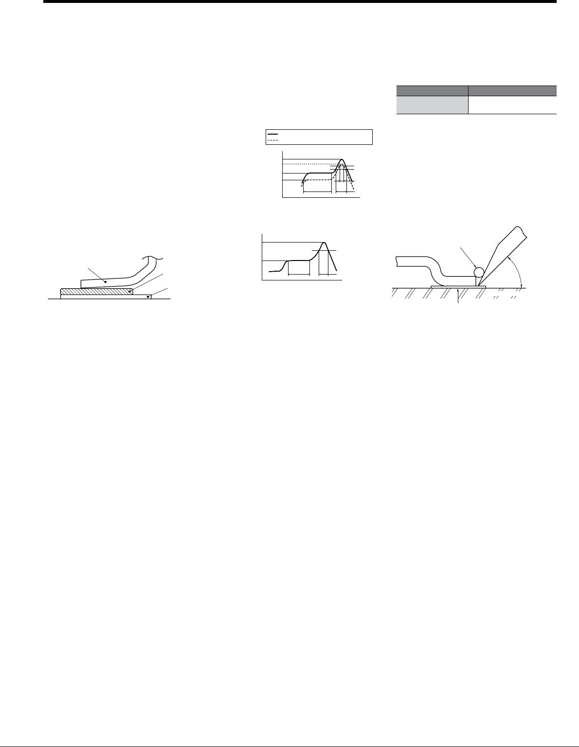
3) Touch the soldering iron to the foot
pattern. After the foot pattern and
connector terminal are heated, apply the
solder wire so it melts at the end of the
connector terminals.
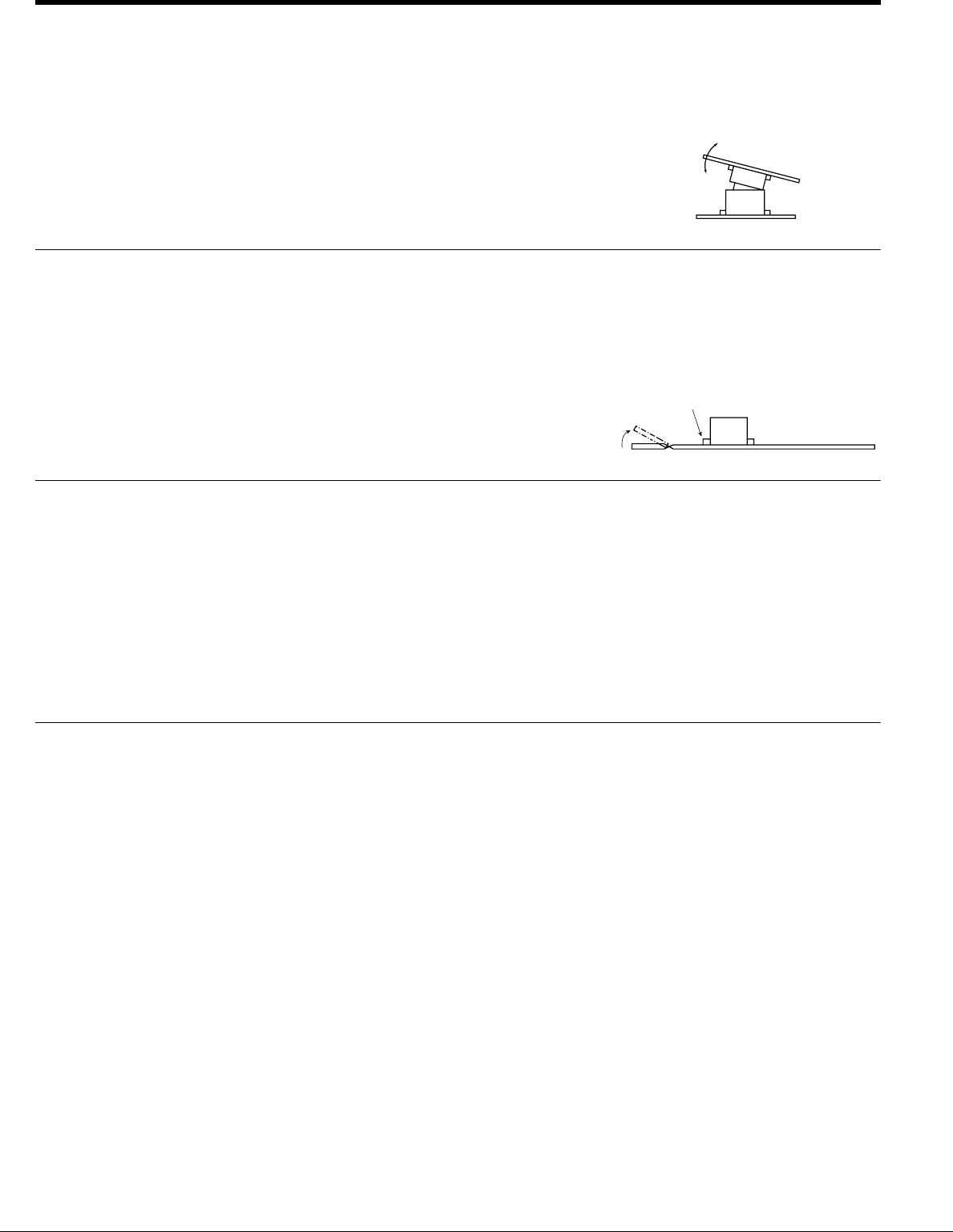
4) Be aware that soldering while applying
a load on the connector terminals may
cause improper operation of the
connector.
5) Thoroughly clean the soldering iron.
6) Flux from the solder wire may get on
the contact surfaces during soldering
operations. After soldering, carefully
check the contact surfaces and clean off
any solder before use.
7) For soldering of prototype devices
during product development, you can
perform soldering at the necessary
locations by heating with a hot-air gun by
applying cream solder to the foot pattern
beforehand. However, at this time, make
sure that the air pressure does not move
connectors by carefully holding them
down with tweezers or other similar tool.
Also, be careful not to go too close to the
connectors and melt any of the molded
components.
8) If an excessive amount of solder is
applied during manual soldering, the
solder may creep up near the contact
points, or solder interference may cause
imperfect contact.
3. Solder reworking
1) Finish reworking in one operation.
2) For reworking of the solder bridge, use
a soldering iron with a flat tip. To prevent
flux from climbing up to the contact
surfaces, do not add more flux.
3) Keep the soldering iron tip temperature
below the temperature given in Table A.
Te rminal
Paste
solder
PC board
foot pattern
60 to 120 sec.
Preheating
Peak temperature
200°C
220°C
Upper limited (Solder heat resistance)
Peak temperature 260°C
230°C
180°C
150°C
70 sec.
25 sec.
Lower limited (Solder wettability)
Time
Temperature
60 to 120 sec.
Preheating
Time
Temperature
Peak temperature
200°C
155 to 165°C
245°C max.
Within 30 sec.
Product name Soldering iron temperature
SMD type connectors
300°C within 5 sec.
350°C within 3 sec.
Apply the solder
wire here
Terminal
Pattern
PC board
Small angle as
possible up to
45 degrees
Soldering
iron