Panasonic Corporation 2013©
Panasonic Corporation Automation Controls Buisiness Division
industrial.panasonic.com/ac/e/
Notes on Using Narrow pitch Connectors
–
9–
ACCTB48E 201303-T
Regarding the design of devices and PC board patterns
Regarding the selection of the connector placement machine and the mounting
procedures
Notes on Using Narrow pitch Connectors
1) When connecting several connectors
together by stacking, make sure to
maintain proper accuracy in the design of
structure and mounting equipment so
that the connectors are not subjected to
twisting and torsional forces.
2) With mounting equipment, there may
be up to a ±0.2 to 0.3-mm error in
positioning. Be sure to design PC boards
and patterns while taking into
consideration the performance and
abilities of the required equipment.
3) Some connectors have tabs embossed
on the body to aid in positioning. When
using these connectors, make sure that
the PC board is designed with positioning
holes to match these tabs.
4) To ensure the required mechanical
strength when soldering the connector
terminals, make sure the PC board
meets recommended PC board pattern
design dimensions given.
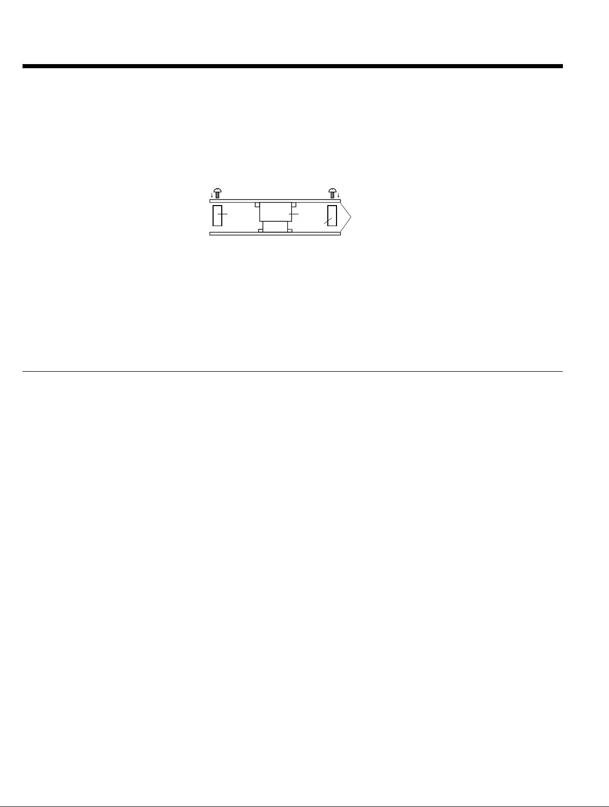
5) For all connectors of the narrow pitch
series, to prevent the PC board from
coming off during vibrations or impacts,
and to prevent loads from falling directly
on the soldered portions, be sure to
design some means to fix the PC board
in place.
Example) Secure in place with screws
When connecting PC boards, take
appropriate measures to prevent the
connector from coming off.
6) Notes when using a FPC.
(1) When the connector is soldered to an
FPC board, during its insertion and
removal procedures, forces may be
applied to the terminals and cause the
soldering to come off. It is recommended
to use a reinforcement board on the
backside of the FPC board to which the
connector is being connected. Please
make the reinforcement board
dimensions bigger than the outer limits of
the recommended PC board pattern
(should be approximately 1 mm greater
than the outer limit).
Material should be glass epoxy or
polyimide, and the thickness should be
between 0.2 and 0.3 mm.
(2) Collisions, impacts, or turning of FPC
boards, may apply forces on the
connector and cause it to come loose.
Therefore, make to design retaining
plates or screws that will fix the connector
in place.
7) The narrow pitch connector series is
designed to be compact and thin.
Although ease of handling has been
taken into account, take care when
mating the connectors, as displacement
or angled mating could damage or
deform the connector.
Connector
Spacer
Spacer
PC board
Screw
1) Select the placement machine taking
into consideration the connector height,
required positioning accuracy, and
packaging conditions.
2) Be aware that if the catching force of
the placement machine is too great, it
may deform the shape of the connector
body or connector terminals.
3) Be aware that during mounting,
external forces may be applied to the
connector contact surfaces and terminals
and cause deformations.
4) Depending on the size of the
connector being used, self alignment
may not be possible. In such cases, be
sure to carefully position the terminal with
the PC board pattern.
5) The positioning bosses give an
approximate alignment for positioning on
the PC board. For accurate positioning of
the connector when mounting it to the PC
board, we recommend using an
automatic positioning machine.
6) Excessive mounter chucking force may
deform the molded or metal part of the
connector. Consult us in advance if
chucking is to be applied.