IDT
TM
/ICST
M
PC MAIN CLOCK 1336—06/01/09
ICS9UMS9610
PC MAIN CLOCK
13
Byte 8 LCD100 PLL M/N Register
Bit
(
s
)
Pin # Name Control Function T
yp
e 0 1 Default
Bit 7
LCD100 N Div8 N Divider Pro
g
bit 8 RW X
Bit 6
LCD100 N Div9 N Divider Pro
g
bit 9 RW X
Bit 5
LCD100 M Div5 RW X
Bit 4
LCD100 M Div4 RW X
Bit 3
LCD100 M Div3 RW X
Bit 2
LCD100 M Div2 RW X
Bit 1
LCD100 M Div1 RW X
Bit 0
LCD100 M Div0 RW X
Byte 9 LCD100 PLL M/N Register
Bit
(
s
)
Pin # Name Control Function T
yp
e 0 1 Default
Bit 7
LCD100 N Div7 RW X
Bit 6
LCD100 N Div6 RW X
Bit 5
LCD100 N Div5 RW X
Bit 4
LCD100 N Div4 RW X
Bit 3
LCD100 N Div3 RW X
Bit 2
LCD100 N Div2 RW X
Bit 1
LCD100 N Div1 RW X
Bit 0
LCD100 N Div0 RW X
Byte 10 Status Readback Register
Bit
(
s
)
Pin # Name Descri
p
tion T
yp
e 0 1 Default
7 37 FSB Frequency Select B R Latch
6 9 FSC Frequency Select C R Latch
5 24 CR0# Readbk Real time CR0# State Indicator R CR0# is Lo
CR0# is Hi
g
hX
4 28 CR1# Readbk Real time CR1# State Indicator R CR1# is Lo
CR1# is Hi
g
hX
3 36 CR2# Readbk Real time CR2# State Indicator R CR2# is Low CR2# is High X
2 Reserved 0
1 Reserved 0
0 Reserved 0
Byte 11 Revision ID/Vendor ID Register
Bit
(
s
)
Pin # Name Descri
p
tion T
yp
e 0 1 Default
7 Rev Code Bit 3 R X
6 Rev Code Bit 2 R X
5 Rev Code Bit 1 R X
4 Rev Code Bit 0 R X
3 Vendor ID bit 3 R 0
2 Vendor ID bit 2 R 0
1 Vendor ID bit 1 R 0
0 Vendor ID bit 0 R 1
The decimal representation of M
and N Divider in Byte 8 and 9 will
configure the DOT VCO
frequency. VCO Frequency =
14.318 x [NDiv(11:0)] /
[MDiv(5:0)]
M Divider Programming
bit (5:0)
N Divider Programming Byte9 bit(7:0) and
Byte8 bit(7:6)
The decimal representation of M
and N Divider in Byte 8 and 9 will
configure the DOT VCO
frequency. VCO Frequency =
14.318 x [NDiv(11:0)] /
[MDiv(5:0)]
Vendor ID
Vendor specific
See Table 1: CPU Frequency
Select Table
Revision ID
IDT
TM
/ICST
M
PC MAIN CLOCK 1336—06/01/09
ICS9UMS9610
PC MAIN CLOCK
14
Byte 12 Device ID Register
Bit
(
s
)
Pin # Name Descri
p
tion T
yp
e 0 1 Default
7 DEV_ID3 Device ID MSB R 1
6 DEV_ID2 Device ID 2 R 0
5 DEV_ID1 Device ID 1 R 1
4 DEV_ID0 Device ID LSB R 0
3 Reserved 0
2 Reserved 0
1 Reserved 0
0 Reserved 0
Byte 13 Reserved Register
Bit
(
s
)
Pin # Name Control Function T
yp
e 0 1 Default
Bit 7
Reserved 0
Bit 6
Reserved 0
Bit 5
Reserved 0
Bit 4
Reserved 0
Bit 3
Reserved 0
Bit 2
Reserved 0
Bit 1
Reserved 0
Bit 0
Reserved 0
Byte 14 Reserved Register
Bit
(
s
)
Pin # Name Control Function T
yp
e 0 1 Default
Bit 7
Reserved 0
Bit 6
Reserved 0
Bit 5
Reserved 0
Bit 4
Reserved 0
Bit 3
Reserved 0
Bit 2
Reserved 0
Bit 1
Reserved 0
Bit 0
Reserved 0
Byte 15 Byte Count Register
Bit
(
s
)
Pin # Name Control Function T
yp
e 0 1 Default
Bit 7
Reserved 0
Bit 6
BC6 Byte Count 6 (MSB) RW 0
Bit 5
BC5 Byte Count 5 RW 0
Bit 4
BC4 Byte Count 4 RW 0
Bit 3
BC3 Byte Count 3 RW 1
Bit 2
BC2 Byte Count 2 RW 1
Bit 1
BC1 Byte Count 1 RW 1
Bit 0
BC0 Byte Count LSB RW 1
Specifies Number of bytes to be
read back during an SMBus
read.
Default is 0xF.
IDT
TM
/ICST
M
PC MAIN CLOCK 1336—06/01/09
ICS9UMS9610
PC MAIN CLOCK
15
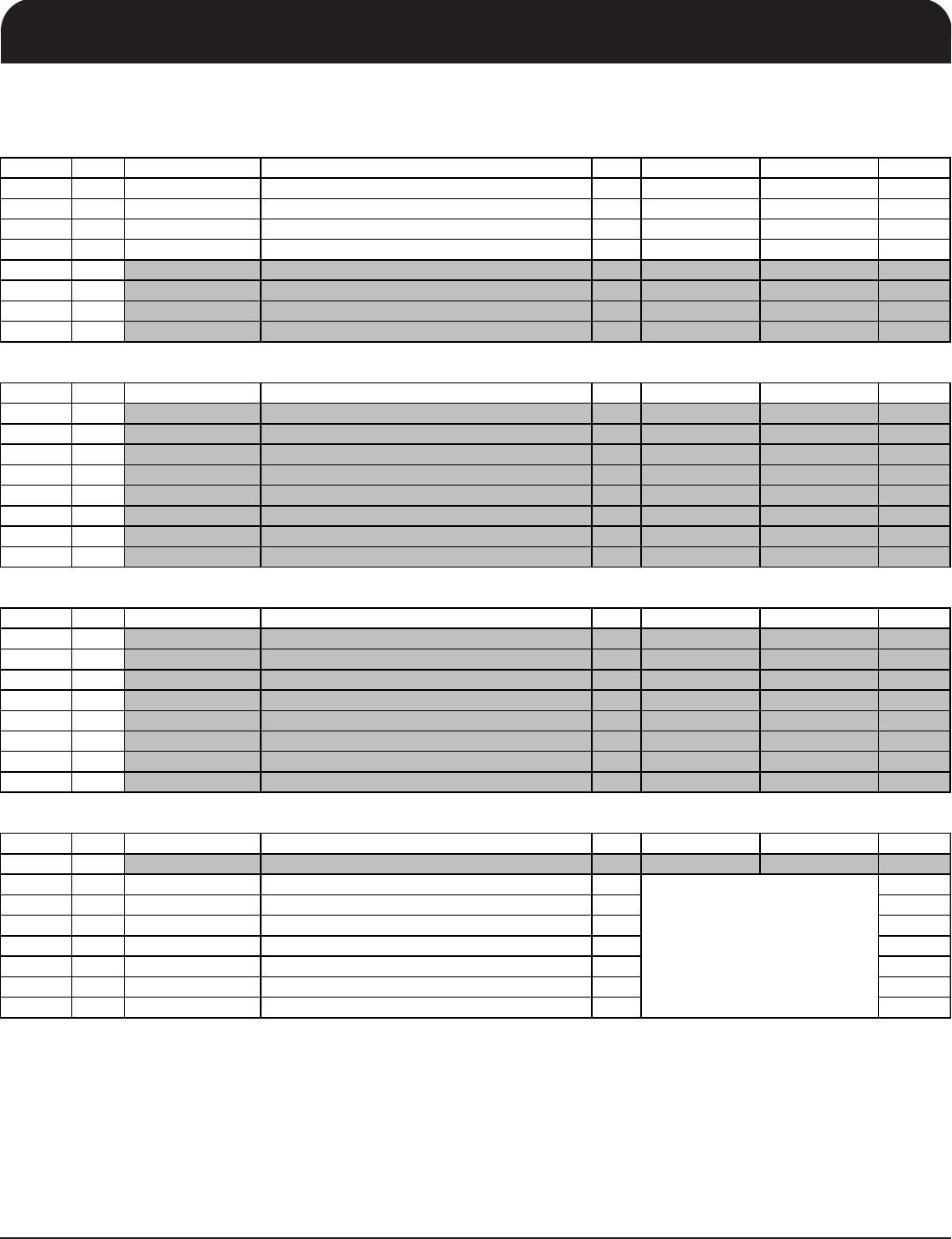
Byte 16 M/N Enable Register
Bit
(
s
)
Pin # Name Control Function T
yp
e 0 1 Default
Bit 7
MN Enable Enables PLL MN pro
g
rammin
g
RW MN Disabled MN Enabled 0
Bit 6
Reserved 0
Bit 5
Reserved 0
Bit 4
Reserved 0
Bit 3
Reserved 0
Bit 2
Reserved 0
Bit 1
Reserved 0
Bit 0
Reserved 0
Byte 17 CPU PLL Spread Spectrum Index Register
Bit
(
s
)
Pin # Name Control Function T
yp
e 0 1 Default
Bit 7
CPUSSP7 RW X
Bit 6
CPUSSP6 RW X
Bit 5
CPUSSP5 RW X
Bit 4
CPUSSP4 RW X
Bit 3
CPUSSP3 RW X
Bit 2
CPUSSP2 RW X
Bit 1
CPUSSP1 RW X
Bit 0
CPUSSP0 RW X
Byte 18 CPU PLL Spread Spectrum Index Register
Bit
(
s
)
Pin # Name Control Function T
yp
e 0 1 Default
Bit 7
CPUSSP15 RW X
Bit 6
CPUSSP14 RW X
Bit 5
CPUSSP13 RW X
Bit 4
CPUSSP12 RW X
Bit 3
CPUSSP11 RW X
Bit 2
CPUSSP10 RW X
Bit 1
CPUSSP9 RW X
Bit 0
CPUSSP8 RW X
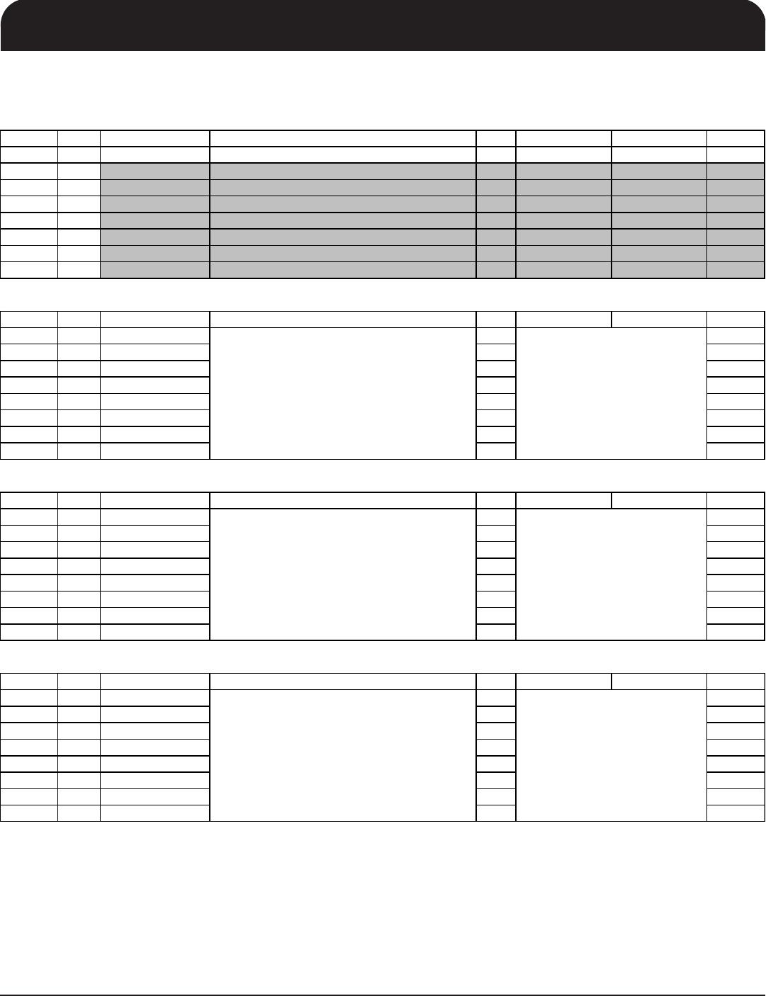
Byte 19 LCD100 PLL Spread Spectrum Index Register
Bit
(
s
)
Pin # Name Control Function T
yp
e 0 1 Default
Bit 7
LCDSSP7 RW X
Bit 6
LCDSSP6 RW X
Bit 5
LCDSSP5 RW X
Bit 4
LCDSSP4 RW X
Bit 3
LCDSSP3 RW X
Bit 2
LCDSSP2 RW X
Bit 1
LCDSSP1 RW X
Bit 0
LCDSSP0 RW X
Spread Spectrum Programming bit(7:0)
Contact IDT before editing these values.
These Spread Spectrum bits in
Byte 19 and 20 will program the
spread percentage of the CPU
and SRC outputs
Spread Spectrum Programming bit(7:0)
Contact IDT before editing these values.
These Spread Spectrum bits in
Byte 17 and 18 will program the
spread percentage of the CPU
and SRC outputs
Spread Spectrum Programming bit(15:8)
Contact IDT before editing these values.
These Spread Spectrum bits in
Byte 17 and 18 will program the
spread percentage of the CPU
and SRC outputs

9UMS9610CKLF

Mfr. #:
Manufacturer:
IDT
Description:
Clock Generators & Support Products LOW VOLTAGE MAIN CLOCK
Lifecycle:
New from this manufacturer.
Delivery:
DHL FedEx Ups TNT EMS
Payment:
T/T Paypal Visa MoneyGram Western Union

Products related to this Datasheet