TWRMC9S08MM128UserManual Page10of13
J20 Accelerometercontrol 12 ConnectsPTB0to0GDETECTpinofaccelerometer
J21 RS232conne ctor Open 2x5RS232connector
J24 Infraredfilterconne ction 12 ChoosewhethertofilterInfraredoutput
J25 Infraredtransmitrouting
12 ConnectsInfraredtransistoroutputtoADP10
34 ConnectsInfraredtransistoroutputtoRX1
56 ConnectseitherIROorTX1toInfrareddiodebaseonJ26
J26 Infraredtransmitrouting
12 TX1pindrivesInfraredtransmit
23 IROpindrivesInfraredtransmit
J27 Medicalboardconnector Open ConnectstoMEDEKGboard
NOTE:Formoredetail,pleaserefertoTWRS08MM128schematicsavailableinthe
TWRS08MM128KIToronFreescale.com/tower.
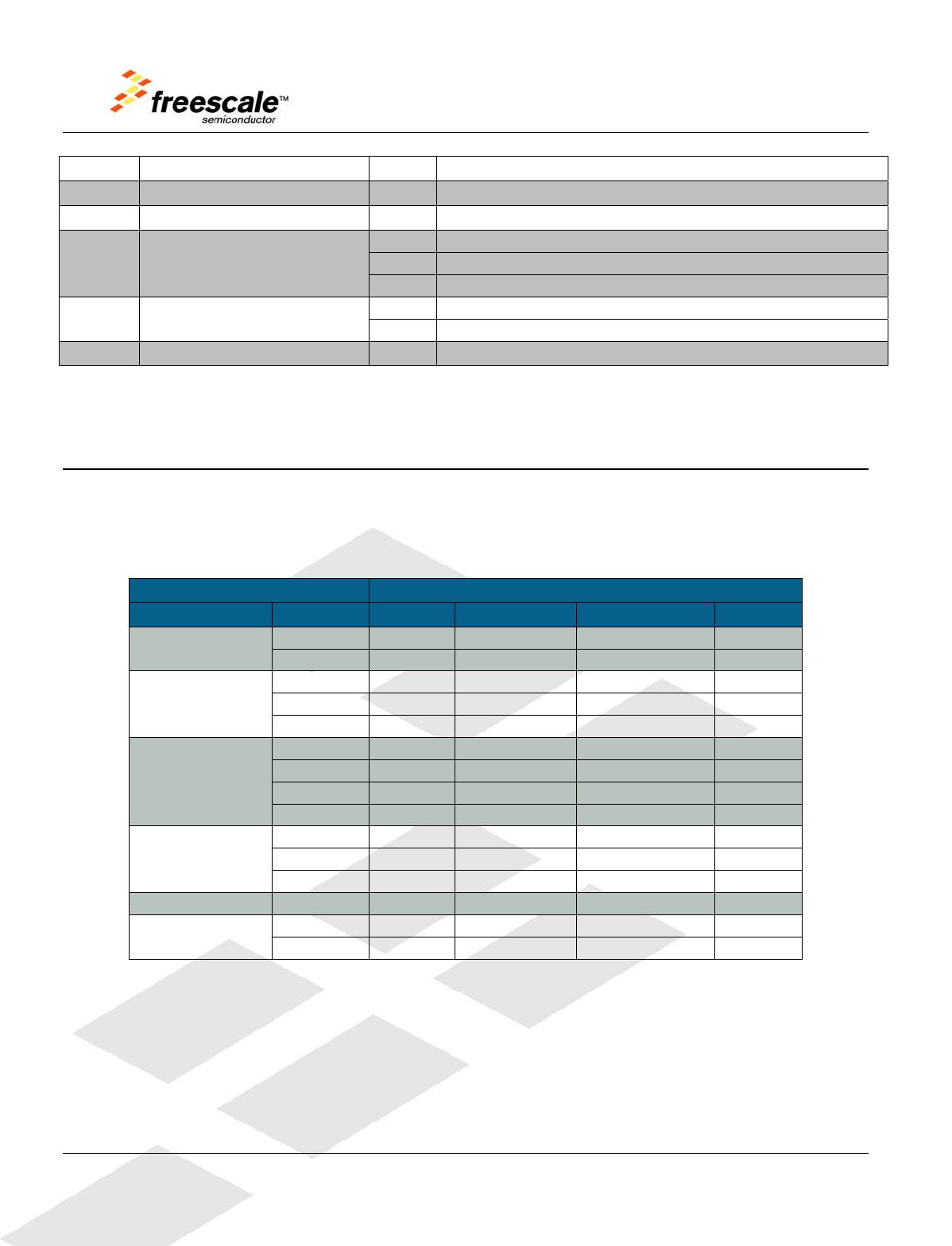
5 Input/OutputConnectorsandPinUsageTable
ThefollowingtablesprovidedetailsonwhichMC9S08MM128pinsarecommunicatingwiththeTWR
MC9S08MMsensors,LEDs,switchesandotherI/Ointerfaces.
Figure6. I/OConnectorsandPinUsageTable
TWRS08MM128 MC9S08MM128
I/OComponent I/OLabel Default Alt1 Alt2 Alt3
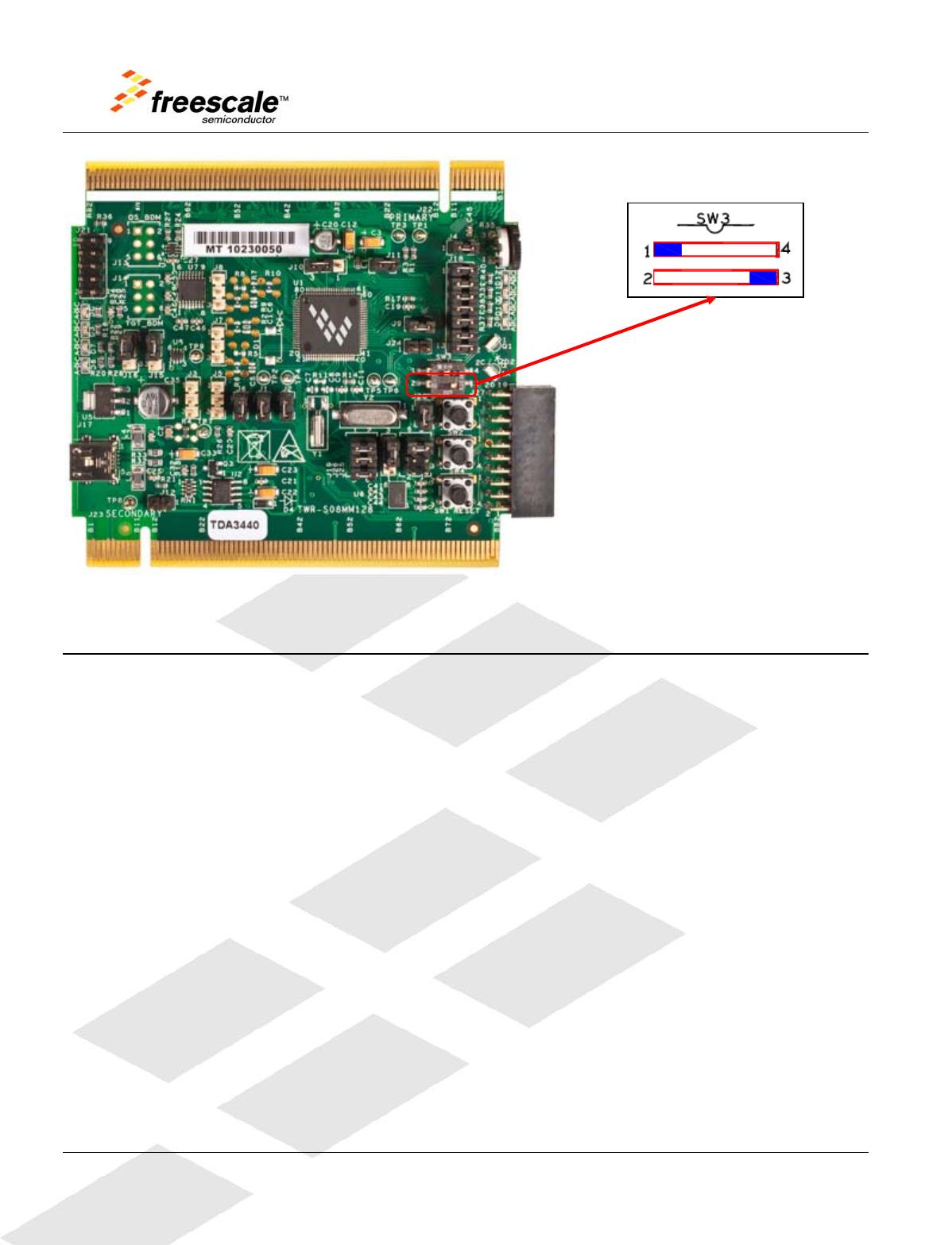
DipSwitch
SW31&4 PTA5 ‐ ‐ ‐
SW32&3 PTB1 /BLMS ‐ ‐
PushButton
SW1 PTD1 CMPP2 /RESET‐
SW2 PTC6 KBI2P1 PRACMPO ADP10
SW4 PTE4 CMPP3 TPMCLK IRQ
LED
LED1(D9) PTF2 TX2 TPM2CH0 ‐
LED2(D10) PTF1 RX2 TPM2CH1 ‐
LED3(D11) PTF0 TPM2CH2 ‐ ‐
LED4(D12) PTE7 TPM2CH3 ‐ ‐
Accelerometer
MMA7361L
X_OUT PTC2 KBI1P5 SPSCK2 ADP6
Y_OUT PTC3 KBI1P6 /SS2 ADP7
Z_OUT PTC4 KBI1P7 CMPP0 ADP8
Potentiometer POT PTA2 KBI1P1 RX1 ADP4
RS232
ICL3232
232_RXD PTE6 RX2‐
232_TXD PTE5 TX2‐
NOTE:LED1toLED4arelabelledasD9toD12ontheTWRS08MM128silkscreen.
TWRMC9S08MM128UserManual Page11of13
6 OSBDM
Anonboard,MC9S08JM60basedOSBDMcircuitprovidesadebuginterfacetotheMC9S08MM128.
TheMC9S08JM60isaUSBenabledmicrocontrollerwithan8bitHC9S08core.TheOSBDMcircuit
providesaUSBtodebuginterfacethatallowsruncontrolanddebuggingoftheMC9S08MM128target
device.TheUSBdriversrequiredtocommunicatewiththeOSBDMareprovidedindevelopmenttools
suchasFreescaleCodeWarrior.WhenTWRS08MM128isusedstandalone,thissingleUSB
connectioncanalsobeusedforpower.
6.1 BootloaderModeForMC9S08JM60
TheMC9S08JM60deviceusedintheOSBDMcircuitispreprogrammedwithOSBDMdebugger
firmwareandaUSBBootloader.ThebootloadermodecanbeusedtoupdatetheOSBDMdebugger
firmwareifanupdatebecomesavailable.JumperJ12determineswhichapplicationwillrunfollowinga
poweronreset.IftheBootloaderModeischosen(jumpershuntonJ12),thebootloaderwillbe
executed,allowingincircuitreprogrammingoftheJM60flashmemoryviaUSB.RefertoApplication
NoteAN3561ontheFreescalewebsite(http://www.freescale.com)fordetailsontheUSBBootloader.
TheUSBBootloadercommunicateswithaGUIapplicationrunningonahostPC.TheGUIapplication
canbefoundontheFreescalewebsite;searchkeyword“JM60GUI.”Refertosection2.5and3.3of
AN3561fordetailsoninstallingandrunningtheapplication.
Note:
TheJM60GUIInstallershouldberunbeforeconnectingtheOSBDMinBootloader
ModetoahostUSBport.Otherwise,theJM60USBdevicewillnotberecognizedand
theproperdriverswillnotbeloaded.
7 BootloaderModeForMC9S08MM128
UnlikeMC9S08JM60,MC9S08MM128hasanonchipROMbasedUSBbootloaderthatallowsthe
MC9S08MM128formasseraseandprogrammingviaitsUSBinterface.Thisonchipbootloaderdoes
notconsumeuserflashspace.ToenableUSBbootloadermodeforMC9S08MM128,ontheTWR
S08MM128module,setSW3DIPswitch2and3toposition3,asindicatedinFigure7.NOTE:Under
normaldevelopmentyouwillneedtosetSW3DIPswitch2and3toposition2.
TWRMC9S08MM128UserManual Page12of13
Figure7.SettingSW3forMC9S08MM128USBbootloadermode
8 BDMinteface(Optional)
BothMC9S08MM128andMC9S08JM60haveanonchipbackgrounddebugmodule.Theusercan
choosetobypasstheUSBOSBDMinterfaceandusetheBDMinterfacefordebuggingand
programmingthecorrespondingchipinstead.TheBDMinterfaceforMC9S08MM128isatJ13header
andMC9S08JM60isatJ14fromtheTWRS08MM128module.TheuserneedsaP&EUSBBDM
MULTILINKinordertousethisinterface.ThisisarepeatfunctionoftheOSBDMandisnotrequired.
Information in this document is provided solely to enable system and software implementers to use Freescale Semiconductor products. There are no
expressorimpliedcopyrightlicensesgrantedhereundertodesignorfabricateanyintegratedcircuitsorintegratedcircuitsbasedontheinformationinthis
document.
FreescaleSemicon ductorreservestherighttomakechangeswithoutfurthernoticetoanyproductsherein.FreescaleSemiconductormakesnowarranty,
representation, or guarantee regarding the suitability of its products for any particular purpose, nor doesFreescale Semiconductor assume any liability
arisingoutoftheapplicationoruseofanyproductorcircuit,andspecificallydisclaimsanyliability,includingwithoutlimitationconsequentialorincidental
damages. “Typical” parameters that may be provided in Freescale Semiconductor data sheets and/or specifications can and do vary in different
applicationsandactualperformancemayvaryovertime.Alloperatingparameters,including“Typicals,”mustbevalidatedforeachcustomerapplication
bycustomer’stechnicalexperts.FreescaleSemiconductordoesnotconveyanylicenseunderitspatentrightsnortherightsofothers.
FreescaleSemiconductorproductsarenotdesigned,intended,orauthorizedforuseascomponentsinsystemsintendedforsurgicalimplantintothebody,
orother applicationsintendedtosupportorsustainlife,orforanyotherapplicationinwhichfailureoftheFreescaleSemiconductorproductcouldcreate
a situation where personal injury or death may occur. Should Buyer purchase or use Freescale Semiconductor products for any such unintended or

TWR-S08MM128-KIT

Mfr. #:
Manufacturer:
NXP / Freescale
Description:
Development Boards & Kits - S08 / S12 For 9S08MM128 USB CAN
Lifecycle:
New from this manufacturer.
Delivery:
DHL FedEx Ups TNT EMS
Payment:
T/T Paypal Visa MoneyGram Western Union

Products related to this Datasheet