TWR‐MC9S08MM128UserManual Page5of13
3.4 RS232Interface
AnRS232transceiverontheTWR‐S08MM128connectstoastandard2x5pinheader(refertoFigure
2).SelectionjumpersJ15andJ16allowMC9S08MM128SCI2signalstoberoutedtoeithertheRS232
transceiverortheOSBDMcircuit.RefertoFigure5formoredetails.
Alternatively,whenassembledasaTowerSystem,theMC9S08MM128SCI1TXandRXareroutedto
theSER‐TWR.IftheSER‐TWRjumpersareconfiguredtoruninRS‐232mode,theSCI1TXandtheRX
signalcanbecommunicatedviatheRS232connectorfromtheTWR‐SER.PleaserefertotheTWR‐SER
usermanual(TWRSERUM)fromwww.freescale.com/towerformoredetail.
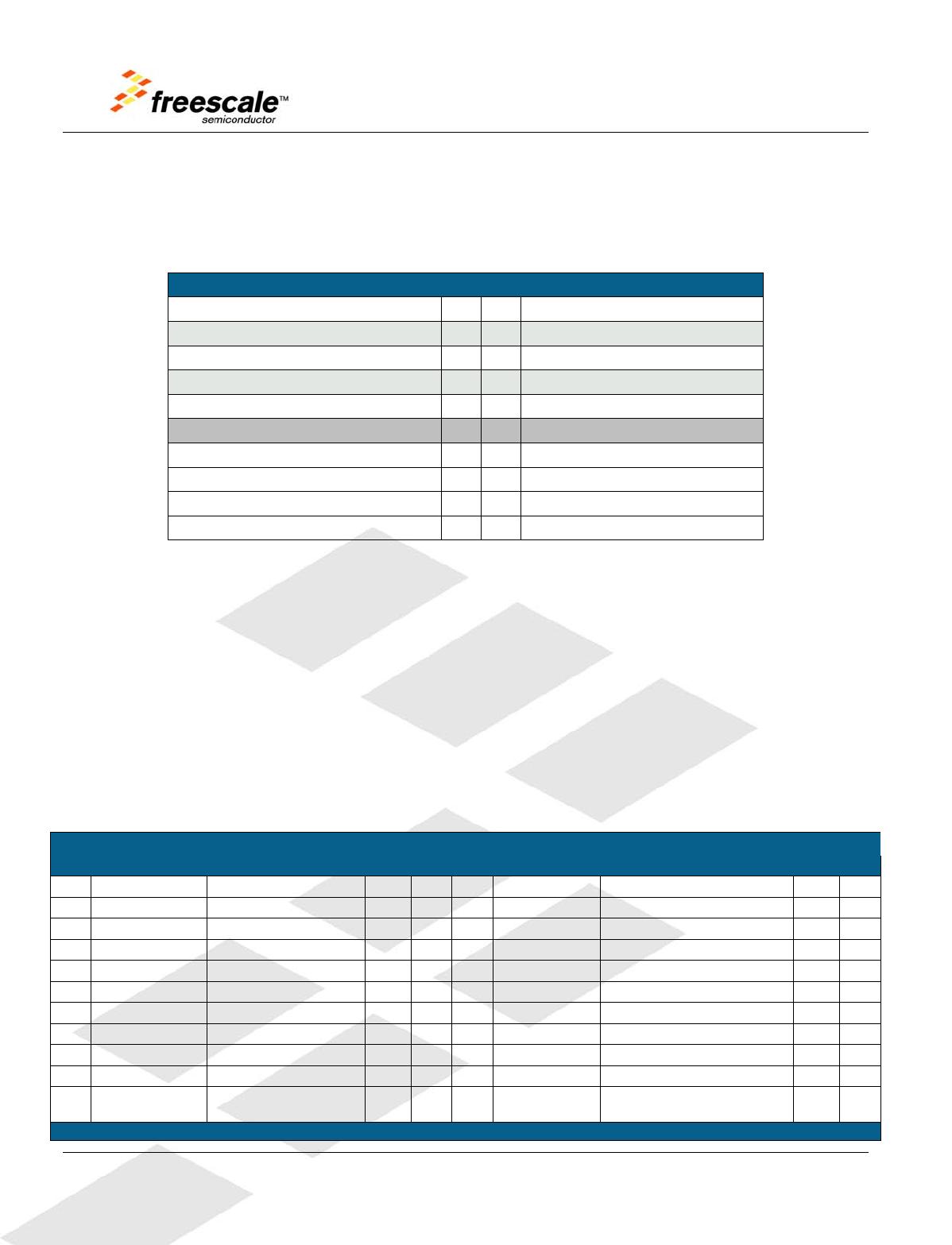
MC9S08MM128
Signal Pin
MC9S08MM128
Signal
NotConnected 1 2 NotConnected
TX2 3 4 NotConnected
RX2 5 6 NotConnected
NotConnected 7 8 NotConnected
GND 9 10 3.3V
Figure2. RS2322x5PinHeaderConnections
3.5 InfraredPort
The TWR‐S08MM128 implements an infrared transmit and receive port. The transmit circuit is
implementedwithaninfrareddiodeandtheusercanchoosetodrivethediodeeitherwithIROorSCI
TX.Thereceiverisimplementedbyaninfraredtransistorandtheusercanchoosetoinputthissignal
totheSCIRXortheACMPinput.JumpersJ9,J25andJ26areusedforroutingtheconnections,referto
Section 4 to set the jumpers. Please refer to application note AN4116, searchable from
www.freescale.com
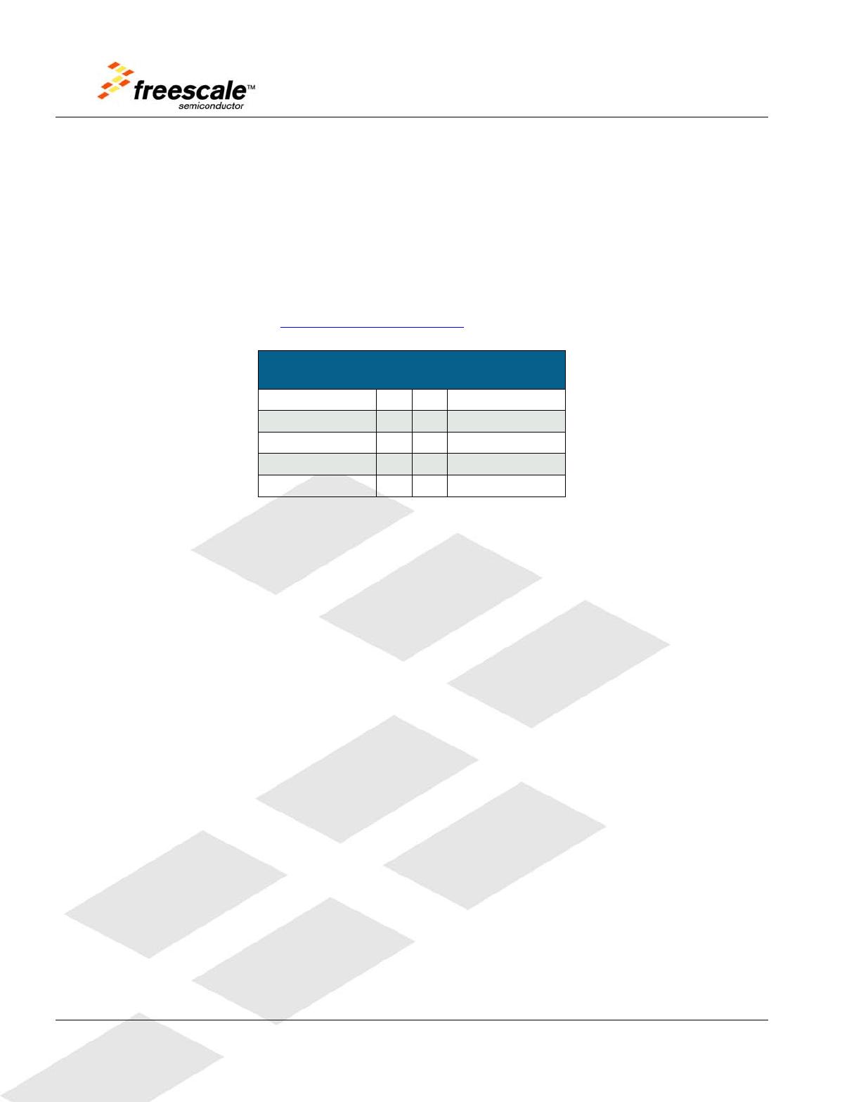
3.6 MedicalConnector
TheTWR‐S08MM128featuresa2x10expansionconnectorJ27(refertoFigure3)toMED‐EKGfor
routingthemedicalenginesignalstoexternalmedicalboardsoitcanusetheOPAMP,TRIAMP,ADC
andDAConMC9S08MM128toimplementtherequirementsignalconditioningformedical
applications.
WhentheDSCMC56F8006fromtheMED‐EKGisenabled,MC9S08MM128canchoosetoreadthe
conditionedEKGresultsoutputfromtheDSCviaI2Ctransmission(pin3andpin4).ToenableI2C
communication,youmustassembletheMEG‐EKGwiththeTowerSystembecausetheTWR‐SERhas
thepulledupresistorscircuitrequiredforI2Ctransmission.
InFigure3,theboldtexthighlightsthefunctionsthatareusedtoimplementtheMED‐EKG
demonstration.FordetailabouttheMED‐EKG,pleaserefertotheMED‐EKGusermanual,MED‐EKGlab