September 2006 Rev 2 1/11
STTH802
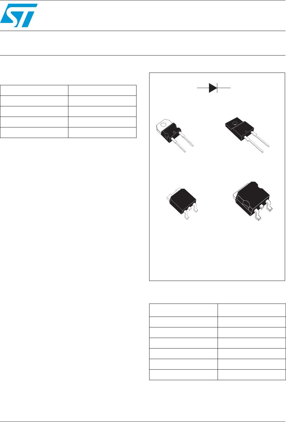
Ultrafast recovery diode
Main product characteristics
Features and benefits
Very low conduction losses
Negligible switching losses
Low forward and reverse recovery time
High junction temperature
Description
The STTH802 uses ST's new 200 V planar Pt
doping technology, and is specially suited for
switching mode base drive and transistor circuits.
Packaged in TO-220AC, TO-220FPAC, DPAK,
and D
2
PAK this device is intended for use in low
voltage, high frequency inverters, free wheeling
and polarity protection.
Order codes
I
F(AV)
8 A
V
RRM
200 V
T
j (max)
175° C
V
F
(typ) 0.8 V
t
rr
(typ) 17 ns
Part Number Marking
STTH802D STTH802
STTH802FP STTH802
STTH802B STTH802
STTH802B-TR STTH802
STTH802G STTH802
STTH802G-TR STTH802
TO-220AC
STTH802D
DPAK
STTH802B
TO-220FPAC
STTH802FP
A
A
A
K
K
K
K
A
A
K
K
NC
NC
DPAK
STTH802G
2
www.st.com
Characteristics STTH802
2/11
1 Characteristics
To evaluate the conduction losses use the following equation:
P = 0.73 x I
F(AV)
+ 0.021 I
F
2
(RMS)
Table 1. Absolute ratings (limiting values at T
j
= 25° C, unless otherwise specified)
Symbol Parameter Value Unit
V
RRM
Repetitive peak reverse voltage 200 V
I
F(RMS)
RMS forward current 16 A
I
F(AV)
Average
forward
current, δ = 0.5
TO-220A, DPAK, D
2
PA K
T
c
= 145° C
8A
TO-220FPAC
T
c
= 125° C
I
FSM
Surge non
repetitive
forward current
t
p
= 10 ms Sinusoidal 100 A
T
stg
Storage temperature range -65 to + 175 ° C
T
j
Maximum operating junction temperature 175 ° C
Table 2. Thermal parameters
Symbol Parameter Value Unit
R
th(j-c)
Junction to case
TO-220AC, DPAK, D
2
PA K 3. 2
° C/W
TO-220FPAC 5.5
Table 3. Static electrical characteristics
Symbol Parameter Test conditions Min. Typ Max. Unit
I
R
(1)
Reverse leakage current
T
j
= 25° C
V
R
= V
RRM
6
µA
T
j
= 125° C 6 60
V
F
(2)
Forward voltage drop
T
j
= 25° C
I
F
= 8 A
0.95 1.05
V
T
j
= 150° C 0.8 0.90
1. Pulse test: t
p
= 5 ms, δ < 2 %
2. Pulse test: t
p
= 380 µs, δ < 2 %
STTH802 Characteristics
3/11
Table 4. Dynamic characteristics
Symbol Parameter
Test conditions
Min. Typ Max. Unit
t
rr
Reverse recovery time
I
F
= 1 A, dI
F
/dt = -50 A/µs,
V
R
= 30 V, T
j
= 25 °C
25 30 ns
I
F
= 1 A, dI
F
/dt = -100 A/µs,
V
R
= 30 V, T
j
= 25 °C
17 22
I
RM
Reverse recovery current
I
F
= 8 A, dI
F
/dt = -200 A/µs,
V
R
= 160 V, T
j
= 125 °C
5.5 7 A
t
fr
Forward recovery time
I
F
= 8 A, dI
F
/dt = 50 A/µs
V
FR
= 1.1 x V
Fmax
, T
j
= 25 °C
150 ns
V
FP
Forward recovery voltage
I
F
= 8 A, dI
F
/dt = 50 A/µs,
T
j
= 25 °C
1.5 V
Figure 1. Peak current versus duty cycle Figure 2. Forward voltage drop versus
forward current (typical values)
0
20
40
60
80
100
0.0 0.1 0.2 0.3 0.4 0.5 0.6 0.7 0.8 0.9 1.0
I
M
(A)
T
d
=tp/T
tp
I
M
T
δ
=tp/T
tp
I
M
P = 2 WP = 2 W
P = 1 WP = 1 W
P = 5 WP = 5 W
δ
0
20
40
60
80
100
120
140
160
180
200
0.0 0.5 1.0 1.5 2.0 2.5 3.0
I
FM
(A)
T
j
=25°C
T
j
=150°C
V
FM
(V)
Figure 3. Forward voltage drop versus
forward current (maximum values)
Figure 4. Relative variation of thermal
impedance, junction to case,
versus pulse duration (TO-220AC,
DPAK, D
2
PAK)
0
20
40
60
80
100
120
140
160
180
200
0.0 0.5 1.0 1.5 2.0 2.5 3.0
I
FM
(A)
T
j
=25°C
T
j
=150°C
V
FM
(V)
0.1
1.0
1.E-03 1.E-02 1.E-01 1.E+00
Z
th(j-c)
/R
th(j-c)
Single pulse
TO-220AC
DPAK
DPAK
2
tp(s)

STTH802G

Mfr. #:
Manufacturer:
STMicroelectronics
Description:
Rectifiers Recovery Diode Ultra Fast
Lifecycle:
New from this manufacturer.
Delivery:
DHL FedEx Ups TNT EMS
Payment:
T/T Paypal Visa MoneyGram Western Union

Products related to this Datasheet