MAX3738
Current Compliance (I
MOD
≤≤
60mA),
DC-Coupled
The minimum voltage at the OUT+ and OUT- pins
is 0.7V.
For:
V
DIODE
= Diode bias point voltage (1.2V typ)
R
L
= Diode bias point resistance (5Ω typ)
R
D
= Series matching resistor (20Ω typ)
For compliance:
V
OUT+
= V
CC
- V
DIODE
- I
MOD
x (R
D
+ R
L
) -
I
BIAS
x R
L
≥ 0.7V
Current Compliance (I
MOD
> 60mA),
AC-Coupled
For applications requiring modulation current greater
than 60mA, headroom is insufficient from proper opera-
tion of the laser driver if the laser is DC-coupled. To
avoid this problem, the MAX3738’s modulation output
can be AC-coupled to the cathode of a laser diode. An
external pullup inductor is necessary to DC-bias the
modulation output at V
CC
. Such a configuration isolates
laser forward voltage from the output circuitry and allows
the output at OUT+ to swing above and below the sup-
ply voltage (V
CC
). When AC-coupled, the MAX3738
modulation current can be programmed up to 85mA.
Refer to Application Note 274:
HFAN-02.0: Interfacing
Maxim Laser Drivers with Laser Diodes
for more informa-
tion on AC-coupling laser drivers to laser diodes.
For compliance:
V
OUT+
= V
CC
- I
MOD
/ 2 x (R
D
+ R
L
) ≥ 0.75V
Determine C
APC
The APC loop filter capacitor (C
APC
) must be selected
to balance the requirements for fast turn-on and mini-
mal interaction with low frequencies in the data pattern.
The low-frequency cutoff is:
C
APC
(µF) ≅ 68 / (f
3dB
(kHz) x (η x
ρ
MON
)
1.1
)
High-frequency noise can be filtered with an additional
cap, C
MD
, from the MD pin to ground.
C
MD
≅ C
APC
/ 4
The MAX3738 is designed so turn-on time is faster than
1ms for most laser gain values (η x
ρ
MON
). Choosing a
smaller value of C
APC
reduces turn-on time. Careful
balance between turn-on time and low-frequency cutoff
may be needed at low data rates for some values of
laser gain.
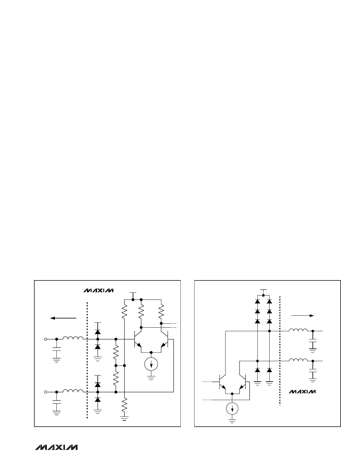
Interface Models
Figures 6 and 7 show simplified input and output cir-
cuits for the MAX3738 laser driver. If dice are used,
replace package parasitic elements with bondwire par-
asitic elements.