MAX3738
155Mbps to 4.25Gbps SFF/SFP Laser Driver
with Extinction Ratio Control
8 _______________________________________________________________________________________
Detailed Description
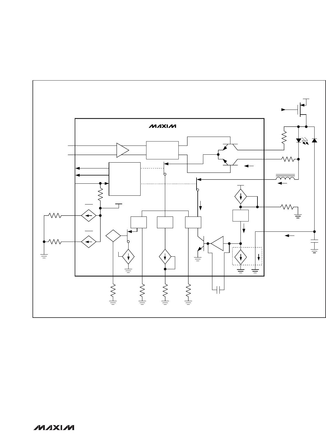
The MAX3738 laser driver consists of three main parts:
a high-speed modulation driver, biasing block with
ERC, and safety circuitry. The circuit design is opti-
mized for high-speed, low-voltage (+3.3V) operation
(Figure 4).
High-Speed Modulation Driver
The output stage is composed of a high-speed differ-
ential pair and a programmable modulation current
source. The MAX3738 is optimized for driving a 15Ω
load. The minimum instantaneous voltage required at
OUT- is 0.7V for modulation currents up to 60mA and
0.75V for currents from 60mA to 85mA. Operation
above 60mA can be accomplished by AC-coupling or
with sufficient voltage at the laser to meet the driver
output voltage requirement.
To interface with the laser diode, a damping resistor
(R
D
) is required. The combined resistance damping
resistor and the equivalent series resistance (ESR) of
the laser diode should equal 15Ω. To further damp
aberrations caused by laser diode parasitic induc-
tance, an RC shunt network may be necessary. Refer to
Application Note 274:
HFAN-02.0: Interfacing Maxim
Laser Drivers with Laser Diodes
for more information.
At high data rates, any capacitive load at the cathode of
a laser diode degrades optical output performance.
Because the BIAS output is directly connected to the
laser cathode, minimize the parasitic capacitance asso-
ciated with the pin by using an inductor to isolate the
BIAS pin parasitics from the laser cathode.
Extinction Ratio Control
The extinction ratio (r
e
) is the laser on-state power
divided by the off-state power. Extinction ratio remains
constant if peak-to-peak and average power are held
constant:
r
e
= (2P
AVG
+ P
P-P
) / (2P
AVG
- P
P-P
)