NORMALIZED WATCHDOG TIMEOUT PERIOD
vs. TEMPERATURE
MAX6854 toc04
TEMPERATURE (°C)
NORMALIZED t
WD
603510-15
0.6
0.8
1.0
1.2
1.4
1.6
1.8
0.4
-40 85
10 100 1000
MAXIMUM V
CC
TRANSIENT DURATION
vs. RESET THRESHOLD OVERDRIVE
MAX684 toc05
RESET THRESHOLD OVERDRIVE (mV)
TRANSIENT DURATION (µs)
1000
0.1
10
1
100
RESET OCCURS ABOVE THIS LINE
V
CC
FALLING FROM V
TH
+100mV
NORMALIZED RESET THRESHOLD VOLTAGE
vs. TEMPERATURE
MAX6854 toc06
TEMPERATURE (°C)
NORMALIZED V
TH
603510-15
0.995
1.000
1.005
1.010
0.990
-40 85
V
CC
TO RESET DELAY
vs. TEMPERATURE
MAX6854 toc07
TEMPERATURE (°C)
t
RD
(µs)
603510-15
30
40
50
60
70
20
-40 85
V
CC
= V
TH
+ 100mV TO V
TH
- 100mV
MAX6854/MAX6855/MAX6856/MAX6858/MAX6860–MAX6869
Nanopower µP Supervisory Circuits with
Manual Reset and Watchdog Timer
4 _______________________________________________________________________________________
Typical Operating Characteristics
(V
CC
= +2.5V, T
A
= +25°C, unless otherwise noted.)
SUPPLY CURRENT
vs. SUPPLY VOLTAGE
MAX6854 toc01
V
CC
(V)
0.1
1.0
10.0
I
CC
(µA)
5.04.53.5 4.02.0 2.5 3.01.51.0 5.5
V
TH
= 2.23V
T
A
= +85°C
T
A
= +25°C
T
A
= -40°C
SUPPLY CURRENT
vs. TEMPERATURE
MAX6854 toc02
TEMPERATURE (°C)
I
CC
(µA)
603510-15
0.12
0.14
0.16
0.18
0.20
0.22
0.10
-40 85
RESET IS NOT ASSERTED
V
TH
= 1.575V
V
CC
= 5.5V
V
CC
= 2.5V
V
CC
= 3.3V
V
CC
= 1.8V
NORMALIZED RESET TIMEOUT PERIOD
vs. TEMPERATURE
MAX6854 toc03
TEMPERATURE (°C)
NORMALIZED t
RP
603510-15
0.99
1.00
1.01
1.02
0.98
-40 85
MAX6854/MAX6855/MAX6856/MAX6858/MAX6860–MAX6869
Nanopower µP Supervisory Circuits with
Manual Reset and Watchdog Timer
_______________________________________________________________________________________ 5
OUTPUT LOW VOLTAGE
vs. SINK CURRENT
MAX6854 toc08
I
SINK
(µA)
V
OL
(V)
4000300020001000
0.05
0.10
0.15
0.20
0.25
0.30
0
05000
V
CC
= 1.8V
V
CC
= 3.3V
V
CC
= 2.5V
OUTPUT HIGH VOLTAGE
vs. SOURCE CURRENT
MAX6854 toc09
I
SOURCE
(µA)
OUTPUT HIGH VOLTAGE (V
CC
- V
OH
) (V)
800600400200
0.05
0.10
0.15
0.20
0.25
0.30
0.35
0.40
0.45
0.50
0
0 1000
V
CC
= 1.8V
V
CC
= 3.3V
V
CC
= 2.5V
SUPPLY CURRENT vs. WATCHDOG
SWITCHING FREQUENCY
MAX6854 toc10
WATCHDOG SWITCHING FREQUENCY (Hz)
SUPPLY CURRENT (µA)
1M100k10k1k100
1
10
100
0.1
10 10M
V
CC
= 2.5V
V
CC
TO RESET DELAY
MAX6854 toc11
10µs/div
200mV/div
1.7V
1.5V
V
CC
RESET
0
1V/div
V
TH
= 1.575V
t
RD
MANUAL RESET DELAY
MAX6854 toc12
200ns/div
1V/div
MR
RESET
1V/div
t
MRD
Typical Operating Characteristics (continued)
(V
CC
= +2.5V, T
A
= +25°C, unless otherwise noted.)
MAX6854/MAX6855/MAX6856/MAX6858/MAX6860–MAX6869
Nanopower µP Supervisory Circuits with
Manual Reset and Watchdog Timer
6 _______________________________________________________________________________________
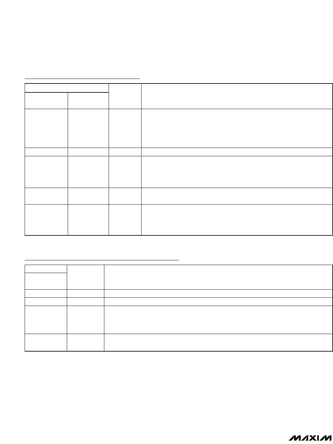
MAX6854/MAX6855/MAX6856 Pin Description
PIN
MAX6854/
MAX6856
MAX6855
NAME FUNCTION
1—RESET
Active-Low Open-Drain or Push-Pull Reset Output. RESET transitions from high to
low when V
CC
drops below the selected reset threshold or MR is pulled low.
RESET remains low for the reset timeout period after V
CC
exceeds the device
reset threshold and MR deasserts. Push-pull RESET outputs are referenced to
V
CC
. Open-drain RESET outputs require an external pullup resistor.
2, 4 2, 4 GND Ground. Connect all GND inputs to the same potential.
33MR
Active-Low Manual Reset Input. Drive MR low to initiate a reset. The reset output
remains asserted while MR is held low and for the reset timeout period after MR
transitions high. Leave MR unconnected or connect to V
CC
if unused. MR is
internally pulled up to V
CC
through 10k.
55V
CC
Supply Voltage. Input for V
CC
reset monitor. For noisy systems, bypass V
CC
with
a 0.1µF capacitor to GND.
—1RESET
Active-High Push-Pull Reset Output. RESET transitions from low to high when
V
CC
drops below the selected reset threshold or MR is pulled low. RESET
remains high for the reset timeout period after V
CC
exceeds the device reset
threshold and MR deasserts. RESET is referenced to V
CC
.
MAX6858/MAX6860 Pin Description
PIN
MAX6858/
MAX6860
NAME FUNCTION
1, 2 I.C. Internally Connected. For increased noise immunity, connect I.C. to GND.
3 GND Ground
4 RESET
Active-Low Open-Drain or Push-Pull Reset Output. RESET transitions from high to low when V
CC
drops below the selected reset threshold. RESET remains low for the reset timeout period after
V
CC
exceeds the device reset threshold. Push-pull RESET outputs are referenced to V
CC
. Open-
drain RESET outputs require an external pullup resistor.
5V
CC
Supply Voltage. Input for V
CC
reset monitor. For noisy systems, bypass V
CC
with a 0.1µF
capacitor to GND.

MAX6864UK23D3S+T

Mfr. #:
Manufacturer:
Maxim Integrated
Description:
Supervisory Circuits Single nPower Supervisor
Lifecycle:
New from this manufacturer.
Delivery:
DHL FedEx Ups TNT EMS
Payment:
T/T Paypal Visa MoneyGram Western Union