Expand menu
Hello, Sign in
My Account
0
Cart
Home
Products
Sensors
Semiconductors
Passive Components
Connectors
Power
Electromechanical
Optoelectronics
Circuit Protection
Integrated Circuits - ICs
Main Products
Manufacturers
Blog
Services
About OMO
About Us
Contact Us
Check Stock
IXYX100N120B3
P1-P3
P4-P6
IXYS Reserves the Right to Change Limits, Test Conditions, and Dimensions.
IXYK100N120B3
IXYX100N120B3
0.001
0.01
0.1
1
0.00001
0.0001
0.001
0.01
0.1
1
10
Puls
e
W
idt
h - S
ec
o
nds
Z
(th)JC
- ºC
/ W
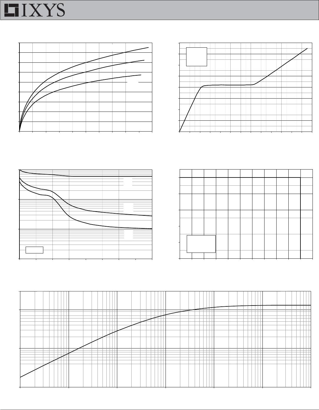
Fig
. 11. Maximu
m Transient
Thermal Imp
edance
aaaaaa
0.3
Fig. 7. Trans
conduc
tanc
e
0
10
20
30
40
50
60
70
80
90
0
20
40
60
80
100
120
140
160
180
200
I
C
- Am
p
eres
g
f s
-
Si
emens
T
J
= -
40ºC
25ºC
150ºC
Fi
g. 10.
Reverse-B
ias Safe Operati
ng
A
rea
0
40
80
120
160
200
200
300
400
500
600
700
800
900
1000
1100
1200
1300
V
CE
- Vol
t
s
I
C
- Amperes
T
J
= 150ºC
R
G
= 1
Ω
dv
/ dt
< 10V / ns
Fig. 8. G
a
te
Cha
rge
0
2
4
6
8
10
12
14
16
0
20
40
60
80
100
120
140
160
180
200
220
240
260
Q
G
- Nan
oCou
lo
m
b
s
V
GE
- Vol
t
s
V
CE
= 600V
I
C
= 100A
I
G
= 10
m
A
Fig. 9. Ca
pacit
anc
e
10
100
1,000
10,000
0
5
10
15
20
25
30
35
40
V
CE
- Vol
ts
Capacit
ance - Pi
coFarads
f
= 1 MH
z
C
ies
C
oes
C
res
© 2013 IXYS CORPORATION, All Rights Reserved
IXYK100N120B3
IXYX100N120B3
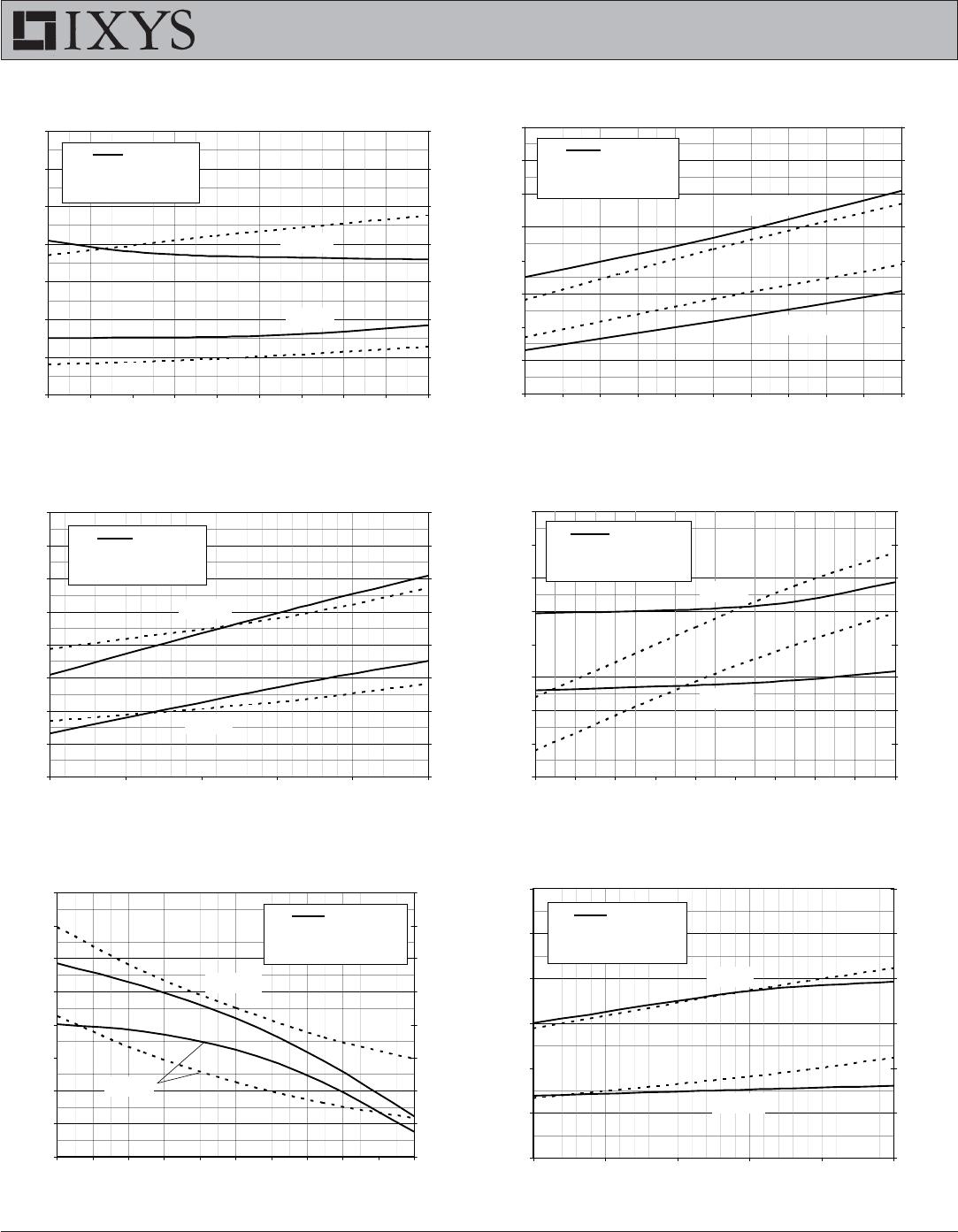
Fig. 12
. Induct
iv
e S
wit
ch
ing Ene
rgy Los
s v
s
.
Gate Resistance
6
7
8
9
10
11
12
13
12345
6789
1
0
R
G
- Oh
m
s
E
off
- M
illiJ
ou
les
4
6
8
10
12
14
16
18
E
on
- M
illiJ
ou
les
E
off
E
on
- - - -
T
J
= 150ºC , V
GE
= 15V
V
CE
= 600V
I
C
= 50
A
I
C
= 100A
Fig. 15
. Induct
ive Turn-off
Sw
it
ching Tim
es
vs
.
Gate Resistance
0
100
200
300
400
500
600
700
800
12345
6789
1
0
R
G
- Oh
m
s
t
f i
- Nanoseconds
150
200
250
300
350
400
450
500
550
t
d
(
off
)
- Nanoseconds
t
f i
t
d(off)
- - - -
T
J
= 150ºC, V
GE
= 15
V
V
CE
= 60
0V
I
C
= 10
0
A
I
C
= 50
A
Fig. 13
. Induct
ive
S
wit
ching E
n
e
rgy Los
s v
s
.
Collec
tor Curre
nt
4
5
6
7
8
9
10
11
12
50
55
60
65
7
0
75
80
85
90
9
5
100
I
C
- A
m
pe
res
E
off
- M
illiJ
ou
les
0
2
4
6
8
10
12
14
16
E
on
- M
illiJ
ou
les
E
off
E
on
- - - -
R
G
= 1
Ω
,
V
GE
= 15
V
V
CE
= 6
00
V
T
J
=
150ºC
T
J
= 25º
C
Fig. 14
. Induct
ive
S
wit
ching E
n
e
rgy Los
s v
s
.
Junc
tion Tem
perat
ure
4
5
6
7
8
9
10
11
12
25
50
75
100
125
150
T
J
- Deg
rees Cent
ig
rad
e
E
off
- M
illiJ
ou
les
0
2
4
6
8
10
12
14
16
E
on
- M
illiJ
ou
les
E
off
E
on
- - - -
R
G
= 1
Ω
,
V
GE
= 15
V
V
CE
= 6
00
V
I
C
= 50A
I
C
=
100A
Fig. 1
6.
Induct
iv
e
T
urn-
of
f S
w
it
ching Tim
es v
s.
Collec
tor Curre
nt
200
250
300
350
400
450
500
550
600
50
55
60
65
70
75
80
85
90
95
100
I
C
- A
m
pe
res
t
f i
- Nanoseconds
130
150
170
190
210
230
250
270
290
t
d(of
f)
- Nanoseconds
t
f i
t
d(off)
- - - -
R
G
= 1
Ω
, V
GE
= 15
V
V
CE
= 60
0
V
T
J
=
150ºC
T
J
= 25
º
C
Fig. 17
. Induc
tiv
e
T
urn-
of
f S
wit
c
hing Tim
es v
s.
Junc
tion Tem
perat
ure
100
200
300
400
500
600
700
25
50
75
100
125
150
T
J
- Deg
r
ee
s Cen
tig
rade
t
f i
- Nanoseconds
100
140
180
220
260
300
340
t
d
(
off
)
- Nanoseconds
t
f i
t
d(off)
- - - -
R
G
= 1
Ω
, V
GE
= 15V
V
CE
= 6
00
V
I
C
= 50A
I
C
=
100A
IXYS Reserves the Right to Change Limits, Test Conditions, and Dimensions.
IXYK100N120B3
IXYX100N120B3
IXYS REF: IXY_100N120B3(9T)12-13-12
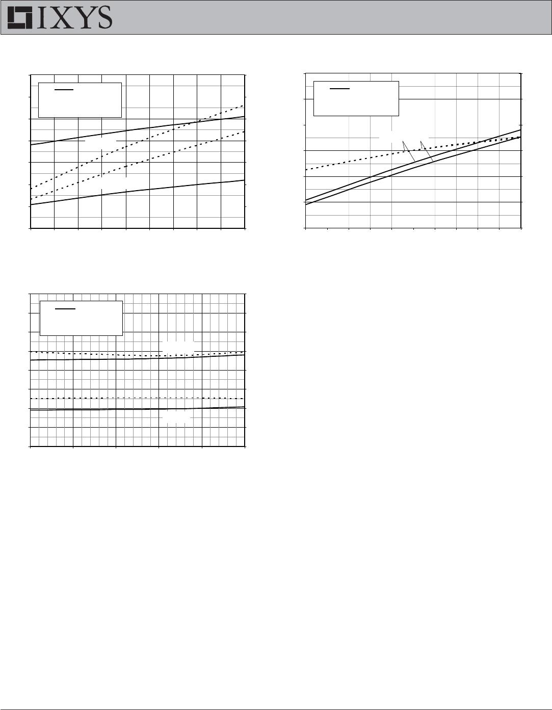
Fig. 19
. Induc
tiv
e
T
urn-
on Sw
itc
hing Tim
es v
s.
Collec
t
or Current
20
40
60
80
100
120
140
50
55
60
65
70
75
80
85
90
95
1
00
I
C
- Am
p
eres
t
r i
- Nanoseconds
22
24
26
28
30
32
34
t
d
(
on
)
- Nanoseconds
t
r i
t
d(on)
- - - -
R
G
= 1
Ω
, V
GE
= 15V
V
CE
= 600V
T
J
= 150ºC, 25ºC
Fig. 20
. Induc
tiv
e
T
urn-
on Sw
itc
hing Tim
es v
s.
Ju
nc
ti
on Tem
pe
ra
tu
re
0
20
40
60
80
100
120
140
160
25
50
75
100
125
150
T
J
- Deg
rees Ce
n
ti
g
rad
e
t
r i
- Nanoseconds
24
25
26
27
28
29
30
31
32
t
d
(
on
)
- Nanoseconds
t
r i
t
d(on)
- - - -
R
G
= 1
Ω
, V
GE
= 15
V
V
CE
= 600V
I
C
= 100A
I
C
= 50A
Fig. 18
. Inductiv
e
T
urn-on S
wit
ching T
im
es
v
s.
Gate R
esistan
ce
20
40
60
80
100
120
140
160
12
3456
789
1
0
R
G
- Oh
m
s
t
r i
- Nanoseconds
20
25
30
35
40
45
50
55
t
d
(
on
)
- Nanoseconds
t
r i
t
d(on)
- - - -
T
J
= 150ºC, V
GE
= 15V
V
CE
= 600V
I
C
= 50A
I
C
= 100A
P1-P3
P4-P6
IXYX100N120B3
Mfr. #:
Buy IXYX100N120B3
Manufacturer:
Littelfuse
Description:
IGBT Transistors DISC IGBT XPT-GENX3
Lifecycle:
New from this manufacturer.
Delivery:
DHL
FedEx
Ups
TNT
EMS
Payment:
T/T
Paypal
Visa
MoneyGram
Western
Union
Products related to this Datasheet
IXYX100N120B3