14
ICM7228
entered when in the shutdown mode. Data is retained in
memory even with the supply voltage as low as 2V.
The ICM7228A/B is shutdown by writing a control word with
Shutdown (lD4) low. The ICM7228C is put into shutdown
mode by driving pin 9, HEXA/CODE B/SHUTDOWN
, low.
The ICM7228 operating current with the display blanked is
within 100A - 200A for all versions. All versions of the
ICM7228 can be blanked by writing Hex FF to all digits and
selecting Code B format. The ICM7228A and ICM7228B can
also be blanked by selecting No Decode mode and writing
Hex 80 to all digits (See Tables 5and 6).
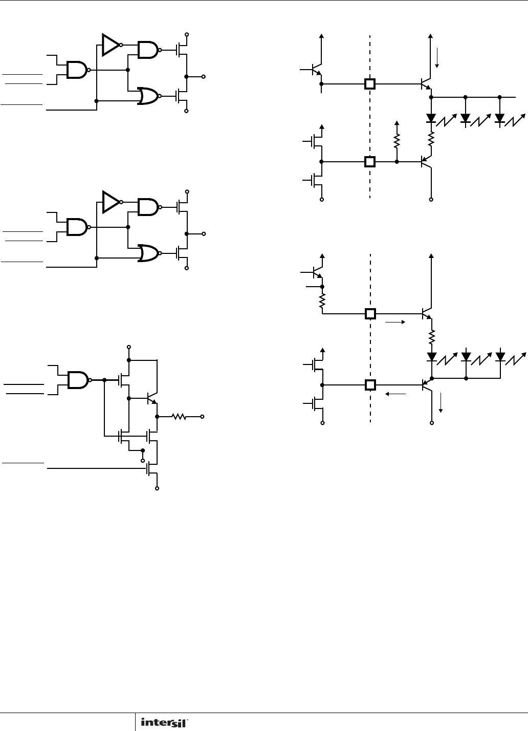
Common Anode Display Drivers, ICM7228A and
ICM7228C
The common anode digit and segment driver output
schematics are shown in Figure 12. The common anode digit
driver output impedance is approximately 4. This provides a
nearly constant voltage to the display digits. Each digit has a
minimum of 200mA drive capability. The N-Channel segment
driver’s output impedance of 50 limits the segment current to
approximately 25mA peak current per segment. Both the
segment and digit outputs can directly drive the display,
current limiting resistors are not required.
Individual segment current is not significantly affected by
whether other segments are on or off. This is because the
segment driver output impedance is much higher than that of
the digit driver. This feature is important in bar graph
applications where each bar graph element should have the
same brightness, independent of the number of elements being
turned on.
Common Cathode Display Driver, ICM7228B
The common cathode digit and segment driver output
schematics are shown in Figure 13. The N-channel digit
drivers have an output impedance of approximately 15.
Each digit has a minimum of 50mA drive capability. The
segment drivers have an output impedance of approximately
100 with typically 10mA peak current drive for each
segment. The common cathode display driver output
currents are only
1
/
4
of the common anode display driver
currents. Therefore, the ICM7228A and ICM7228C common
anode display drivers are recommended for those
applications where high display brightness is desired. The
ICM7228B common cathode display driver is suitable for
driving bubble-lensed monolithic 7 segment displays. They
can also drive individual LED displays up to 0.3 inches in
height when high brightness is not required.
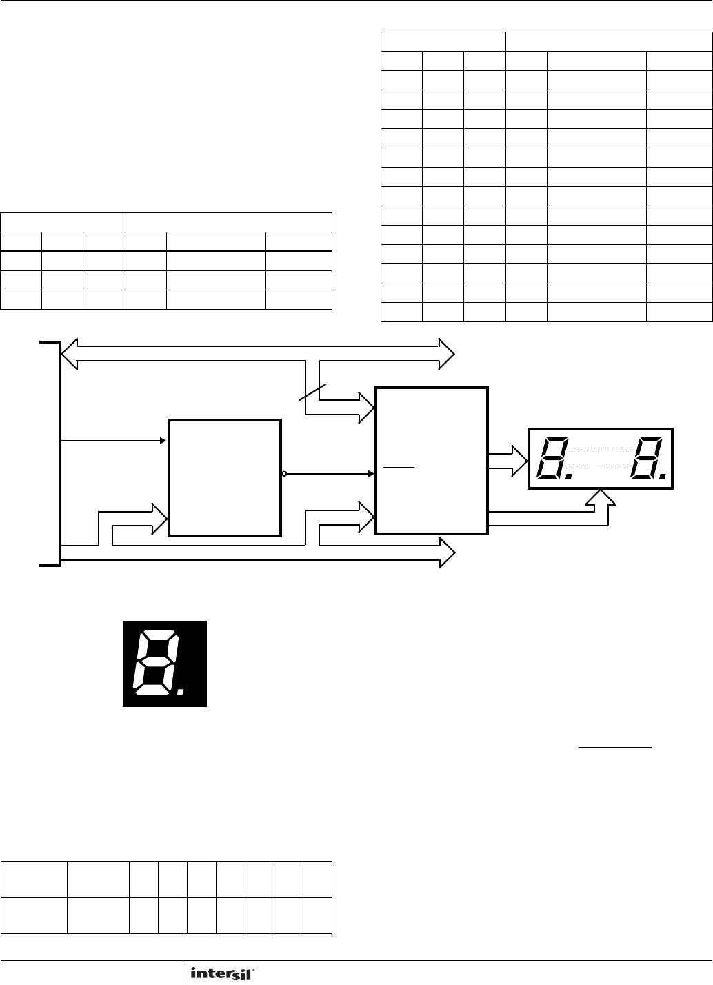
Display Multiplexing
Each digit of the ICM7228 is on for approximately 320s,
with a multiplexing frequency of approximately 390Hz. The
ICM7228 display drivers provide interdigit blanking. This
ensures that the segment information of the previous digit is
gone and the information of the next digit is stable before the
next digit is driven on. This is necessary to eliminate display
ghosting (a faint display of data from previous digit
superimposed on the next digit). The interdigit blanking time
is 10s typical with a guaranteed 2s minimum. The
ICM7228 turns off both the digit drivers and the segment
drivers during the interdigit blanking period. The digit
multiplexing sequence is: D2, D5, D1, D7, D8, D6, D4 and
D3. A typical digit’s drive pulses are shown on Figure 4.
Due to the display multiplexing, the driving duty cycle for
each digit is 12% (100 x
1
/
8
) This means the average current
for each segment is
1
/
8
of its peak current. This must be
considered while designing and selecting the displays.
Driving Larger Displays
If very high display brightness is desired, the ICM7228
display driver outputs can be externally buffered. Figures 14
thru 16 show how to drive either common anode or common
cathode displays using the ICM7228 and external driver
circuit for higher current displays.
Another method of increasing display currents is to connect
two digit outputs together and load the same data into both
digits. This drives the display with the same peak current,
but the average current doubles because each digit of the
display is on for twice as long, i.e.,
1
/
4
duty cycle versus
1
/
8
.
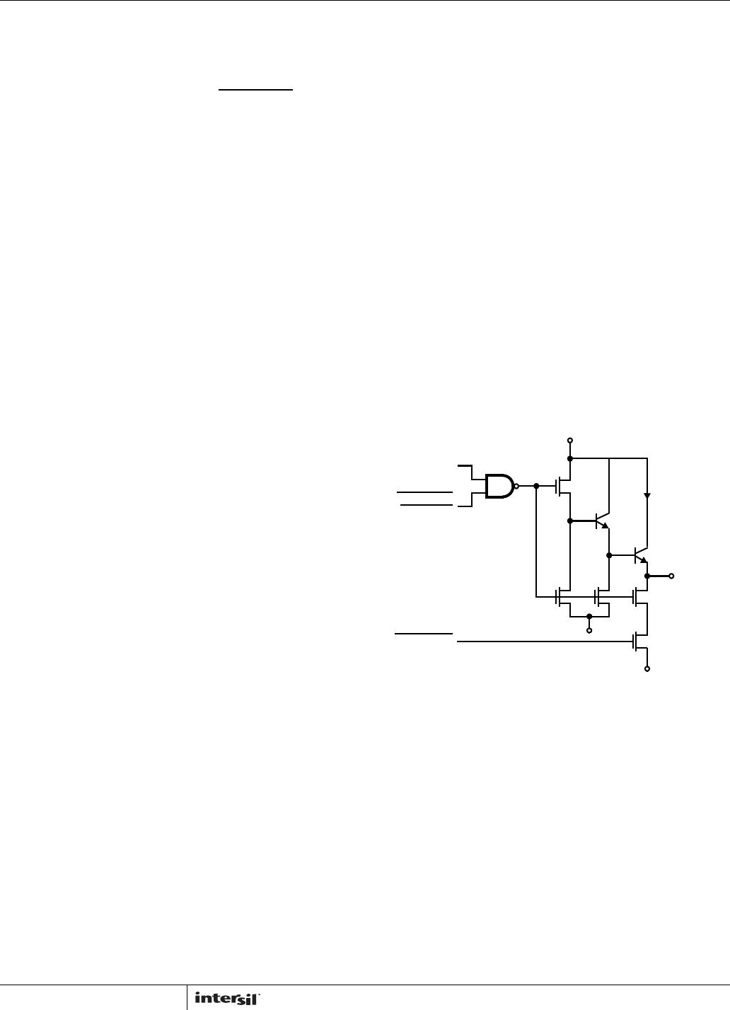
DIGIT
STROBE
INTERDIGIT
BLANKING
SHUTDOWN
V
DD
200mA
COMMON
ANODE
DIGIT
OUTPUT
2k
N
V
SS
P
2k
N
V
SS
N
N
NOTE: When SHUTDOWN goes low INTERDIGIT BLANKING also
stays low.
FIGURE 12A. DIGIT DRIVER