VJ....31 / VJ....34 Automotive MLCC
www.vishay.com
Vishay Vitramon
Alternative Device Available, See GA....31G and GA....34G Automotive MLCC
Revision: 31-Jan-17
1
Document Number: 45040
For technical questions, contact: mlcc@vishay.com
THIS DOCUMENT IS SUBJECT TO CHANGE WITHOUT NOTICE. THE PRODUCTS DESCRIBED HEREIN AND THIS DOCUMENT
ARE SUBJECT TO SPECIFIC DISCLAIMERS, SET FORTH AT www.vishay.com/doc?91000
Surface Mount Multilayer Ceramic Chip Capacitors
for Automotive Applications
FEATURES
AEC-Q200 qualified with PPAP available
Available in 0402 to 1812 body size
Four dielectric materials
AgPd termination available for silver epoxy
bonding
High operating temperature
Wet build process
Reliable Noble Metal Electrode (NME) system
RoHS and ELV (end-of-life vehicles) compliance, see
Selection Charts
Material categorization: for definitions of compliance
please see www.vishay.com/doc?99912
Note
*
This datasheet provides information about parts that are
RoHS-compliant and / or parts that are non RoHS-compliant. For
example, parts with lead (Pb) terminations are not RoHS-compliant.
Please see the information / tables in this datasheet for details
For more than 25 years Vishay Vitramon has supported the automotive industry with robust, highly reliable MLCCs that have
made it a leader in this segment. All Vishay Vitramon MLCCs are manufactured in “Precious Metal Technology” (PMT / NME)
and a wet build process. They are qualified according to AEC-Q200 with PPAP available on request. Applications for these
devices include automotive “under the hood”, safety and comfort electronics. Their termination finish is 100 % matte tin plate
finish and AgPd which is used with silver epoxy bonding. A polymer (flexible) termination with 100 % matte tin plate finish is
offered for boardflex sensitive applications.
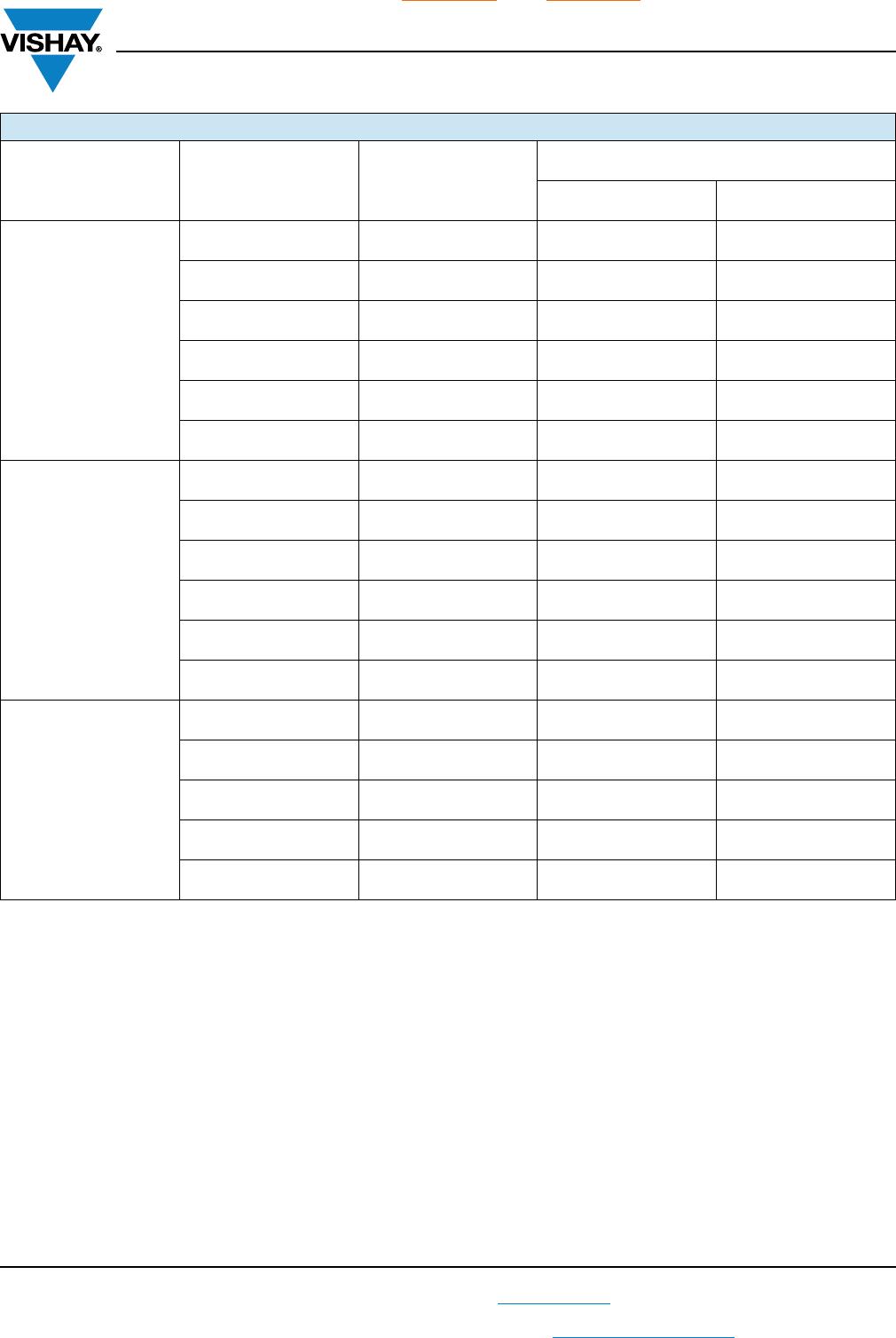

Available
C0G (NP0) DIELECTRIC
GENERAL SPECIFICATION
Note
Electrical characteristics at +25 °C unless otherwise specified
Operating Temperature: -55 °C to +150 °C
(above +125 °C changed characteristics, see 2.3)
Capacitance Range: 1 pF to 22 nF
Voltage Range: 25 V
DC
to 3000 V
DC
Temperature Coefficient of Capacitance (TCC):
0 ppm/°C ± 30 ppm/°C from -55 °C to +125 °C
Dissipation Factor (DF):
0.1 % maximum at 1.0 V
RMS
and
1 MHz for values 1000 pF
0.1 % maximum at 1.0 V
RMS
and
1 kHz for values > 1000 pF
Insulating Resistance:
at +25 °C 100 000 M min. or 1000 F whichever is less
at +125 °C 10 000 M min. or 100 F whichever is less
Aging
: 0 % maximum per decade
Dielectric Strength Test:
performed per method 103 of EIA 198-2-E.
Applied test voltages
250 V
DC
-rated: 250 % of rated voltage
500 V
DC
-rated: 200 % of rated voltage
630 V
DC
, 1000 V
DC
-rated: 150 % of rated voltage
3000 V
DC
-rated: 120 % of rated voltage
X7R, X8R DIELECTRIC
GENERAL SPECIFICATION
Note
Electrical characteristics at +25 °C unless otherwise specified
Operating Temperature: -55 °C to +150 °C
(X7R above +125 °C changed characteristics, see 2.3)
Capacitance Range
: 120 pF to 1.0 μF
Voltage Range
: 16 V
DC
to 1000 V
DC
Temperature Coefficient of Capacitance (TCC):
X7R: ± 15 % from -55 °C to +125 °C, with 0 V
DC
applied
X8R: ± 15 % from -55 °C to +150 °C, with 0 V
DC
applied
Dissipation Factor (DF):
10 V ratings: 5 % maximum at 1.0 V
RMS
and 1 kHz
16 V, 25 V ratings: 3.5 % maximum at 1.0 V
RMS
and 1 kHz
> 25 V ratings: 2.5 % maximum at 1.0 V
RMS
and 1 kHz
Insulating Resistance:
at +25 °C 100 000 M min. or 1000 F whichever is less
at +125 °C 10 000 M min. or 100 F whichever is less
Aging Rate: 1 % maximum per decade
Dielectric Strength Test:
performed per method 103 of EIA 198-2-E.
Applied test voltages
250 V
DC
-rated: 250 % of rated voltage
500 V
DC
-rated: min. 150 % of rated voltage
630 V
DC
, 1000 V
DC
-rated: min. 120 % of rated voltage
VJ....31 / VJ....34 Automotive MLCC
www.vishay.com
Vishay Vitramon
Alternative Device Available, See GA....31G and GA....34G Automotive MLCC
Revision: 31-Jan-17
2
Document Number: 45040
For technical questions, contact: mlcc@vishay.com
THIS DOCUMENT IS SUBJECT TO CHANGE WITHOUT NOTICE. THE PRODUCTS DESCRIBED HEREIN AND THIS DOCUMENT
ARE SUBJECT TO SPECIFIC DISCLAIMERS, SET FORTH AT www.vishay.com/doc?91000
Note
Detail ratings see “Selection Chart”
QUICK REFERENCE DATA
DIELECTRIC CASE CODE
MAXIMUM VOLTAGE
(V)
CAPACITANCE
MINIMUM MAXIMUM
C0G (NP0)
0402 100 1.0 pF 220 pF
0603 200 1.0 pF 1.0 nF
0805 500 1.0 pF 3.9 nF
1206 630 1.0 pF 10 nF
1210 630 100 pF 12 nF
1812 3000 27 pF 22 nF
X7R
0402 100 120 pF 47 nF
0603 200 330 pF 150 nF
0805 500 330 pF 470 nF
1206 630 220 pF 1.0 μF
1210 630 390 pF 1.0 μF
1812 630 10 nF 1.0 μF
X8R
0402 100 330 pF 6.8 nF
0603 100 470 pF 33 nF
0805 100 470 pF 100 nF
1206 50 1.0 nF 220 nF
1210 50 10 nF 390 nF
VJ....31 / VJ....34 Automotive MLCC
www.vishay.com
Vishay Vitramon
Alternative Device Available, See GA....31G and GA....34G Automotive MLCC
Revision: 31-Jan-17
3
Document Number: 45040
For technical questions, contact: mlcc@vishay.com
THIS DOCUMENT IS SUBJECT TO CHANGE WITHOUT NOTICE. THE PRODUCTS DESCRIBED HEREIN AND THIS DOCUMENT
ARE SUBJECT TO SPECIFIC DISCLAIMERS, SET FORTH AT www.vishay.com/doc?91000
Notes
(1)
DC voltage rating should not be exceeded in application. Other application factors may affect the MLCC performance.
Consult for questions: mlcc@vishay.com
(2)
Case size designator may be replaced by a four digit drawing number
(3)
Polymer termination for size 0603 and larger, contact mlcc@vishay.com for availability of ratings. Packaging only plastic tape “T” / “R”
(4)
Non-standard values please contact: mlcc@vishay.com for availability
(5)
Packaging “T” and “R” is used for 1812 size
(6)
Termination code “E” is for conductive epoxy assembly.
(7)
Termination code “B” and “F” are not available with X8R in 0402, 0603 - 100 V, 0805 - 100 V.
ORDERING INFORMATION - TIN TERMINATION
VJ0805
(2)
Y102 K X A A C31
CASE
CODE
DIELECTRIC CAPACITANCE
NOMINAL
CODE
(4)
CAPACITANCE
TOLERANCE
TERMINATION DC VOLTAGE
RATING
(1)
MARKING PACKAGING PROCESS
CODE
0402
0603
0805
1206
1210
1812
A = C0G
(NP0)
Y = X7R
H = X8R
Expressed in
picofarads (pF).
The first two
digits are
significant, the
third is a
multiplier. An
“R” indicates a
decimal point.
Examples
4R7 = 4.7 pF
102 = 1000 pF
B = ± 0.10 pF
C = ± 0.25 pF
D = ± 0.5 pF
F = ± 1 %
G = ± 2 %
J = ± 5 %
K = ± 10 %
M = ± 20 %
Note:
C0G (NP0):
B, C, D < 10 pF
F, G, J, K 10 pF
X7R / X8R:
J, K, M
X = Ni barrier
100 % matte tin
plate finish
B = polymer
100 % matte tin
plate finish
(3)(7)
J = 16 V
X = 25 V
A = 50 V
B = 100 V
C = 200 V
P = 250 V
E = 500 V
L = 630 V
G = 1000 V
H = 3000 V
A = unmarked
B = marked
Note:
marking is only
available for
0805 and 1206
vendor ID and
date code
31 =
automotive
100 %
matte tin
plate finish
E / T = 7" reel / plastic tape
(5)
C = 7" reel / paper tape
M / R = 11 1/4" / 13" reel / plastic tape
(5)
P = 11 1/4" / 13" reel / paper tape
ORDERING INFORMATION - SILVER PALLADIUM TERMINATION
VJ0805
(2)
Y102 K F A A O34
CASE
CODE
DIELECTRIC CAPACITANCE
NOMINAL
CODE
(4)
CAPACITANCE
TOLERANCE
TERMINATION DC VOLTAGE
RATING
(1)
MARKING PACKAGING PROCESS
CODE
0402
0603
0805
1206
1210
1812
A = C0G
(NP0)
Y = X7R
H = X8R
Expressed in
picofarads (pF).
The first two
digits are
significant, the
third is a
multiplier. An
“R” indicates a
decimal point.
Examples
102 = 1000 pF
B = ± 0.10 pF
C = ± 0.25 pF
D = ± 0.5 pF
F = ± 1 %
G = ± 2 %
J = ± 5 %
K = ± 10 %
M = ± 20 %
Note:
C0G (NP0):
B, C, D < 10 pF
F, G, J, K 10 pF
X7R / X8R:
J, K, M
F, E = AgPd
(6)(7)
J = 16 V
X = 25 V
A = 50 V
B = 100 V
C = 200 V
P = 250 V
E = 500 V
L = 630 V
G = 1000 V
H = 3000 V
A = unmarked
Note:
marking is not
available
34 =
automotive
AgPd finish
E / T = 7" reel / plastic tape
(5)
O = 7" reel / flamed paper tape
M / R = 11 1/4" / 13" reel / plastic tape
(5)
I = 11 1/4" / 13" reel / flamed paper tape
Note:
“I” and “O” are used for
“F”, “E” termination
size 0402 / 0603 / 0805

VJ0603Y222KXCAC31

Mfr. #:
Manufacturer:
Vishay
Description:
Multilayer Ceramic Capacitors MLCC - SMD/SMT 0603 2200pF 200volts X7R 10%
Lifecycle:
New from this manufacturer.
Delivery:
DHL FedEx Ups TNT EMS
Payment:
T/T Paypal Visa MoneyGram Western Union