9
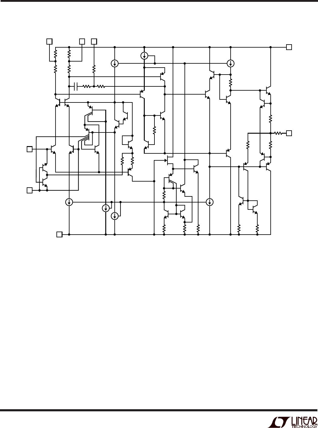
LT1097
15V
–15V
OUT
LT1097•F01
4
3
2
7
6
50k
50k
50k
50k
+IN
–IN
+
–
LT1097
V–
OUT
V+
LT1097•F02
4
5
C
S
1
3
2
10k
POT
8
7
6
+
–
LT1097
Frequency Compensation and Optional Offset Nulling±27V Common Mode Range Difference Amplifier
APPLICATIONS INFORMATION
WUU
U
Guaranteed Perfomance, V
S
= ±15V, T
A
= 25°C
PARAMETER LT1097CN8 OP-77GP AD707JN OP-177GP OP-97FP UNITS
Error Terms
V
OS
Max 50 100 90 60 75 µV
I
OS
Max•25k 6 70 50 70 4 µV
Gain Min, 10V Out 14 5 3 5 50 µV
CMRR, Min, ±25V In 22 20 13 22 39 µV
PSRR, Min, V
S
= ±15V ±10% 69999 µV
Sum of All Error Terms 98 204 165 166 177 µV
0.1Hz to 10Hz Noise
Voltage Noise 0.5 0.38 0.23 0.38 0.5 µVp-p Typ
Current Noise•50k 0.11 0.75 0.7 0.75 0.1 µVp-p Typ
Resistor Noise 0.55 0.55 0.55 0.55 0.55 µVp-p Typ
RMS sum 0.75 1 0.92 1 0.75 µVp-p
Drift with Temp
TCV
OS
Max 1 1.2 1 1.2 2 µV/°C
TCI
OS
Max•25k 0.1 2.1 1 2.1 0.2 µV/°C
Sum of Drift Terms 1.1 3.3 2 3.3 2.2 µV/°C
Supply Current Max 0.56 2 3 2 0.6 mA
The LT1097 is pin compatible to and directly replaces such
precision op amps as the OP-07, OP-77, AD707, OP-97, OP-
177, LM607 and LT1001 with improved price/performance.
Compatibility includes externally nulling the offset voltage, as
all of the above devices are trimmed with a potentiometer
between Pin 1 and Pin 8 and the wiper tied to V
+
.
The simple difference amplifier can be used to illustrate
the all-around excellence of the LT1097. The 50k input
resistance is selected to be large enough compared to
input signal source resistance. Simultaneously, the 50k
resistors should not dominate the precision and noise
error budget. Assuming perfect matching between the
four resistors, the following table summarizes the input
referred performance obtained using the LT1097 and
other popular, low cost precision op amps.
Input offset voltage can be adjusted over a ±600µV range
with a 10k potentiometer.
The LT1097 is internally compensated for unity gain
stability. As shown on the Capacitive Load Handling plot,
the LT1097 is stable with any capacitive load. However,
the overcompensation capacitor, C
S
, can be used to re-
duce overshoot with heavy capacitive loads, to narrow
noise bandwidth or to stabilize circuits with gain in the
feedback loop.