7/17
L9903
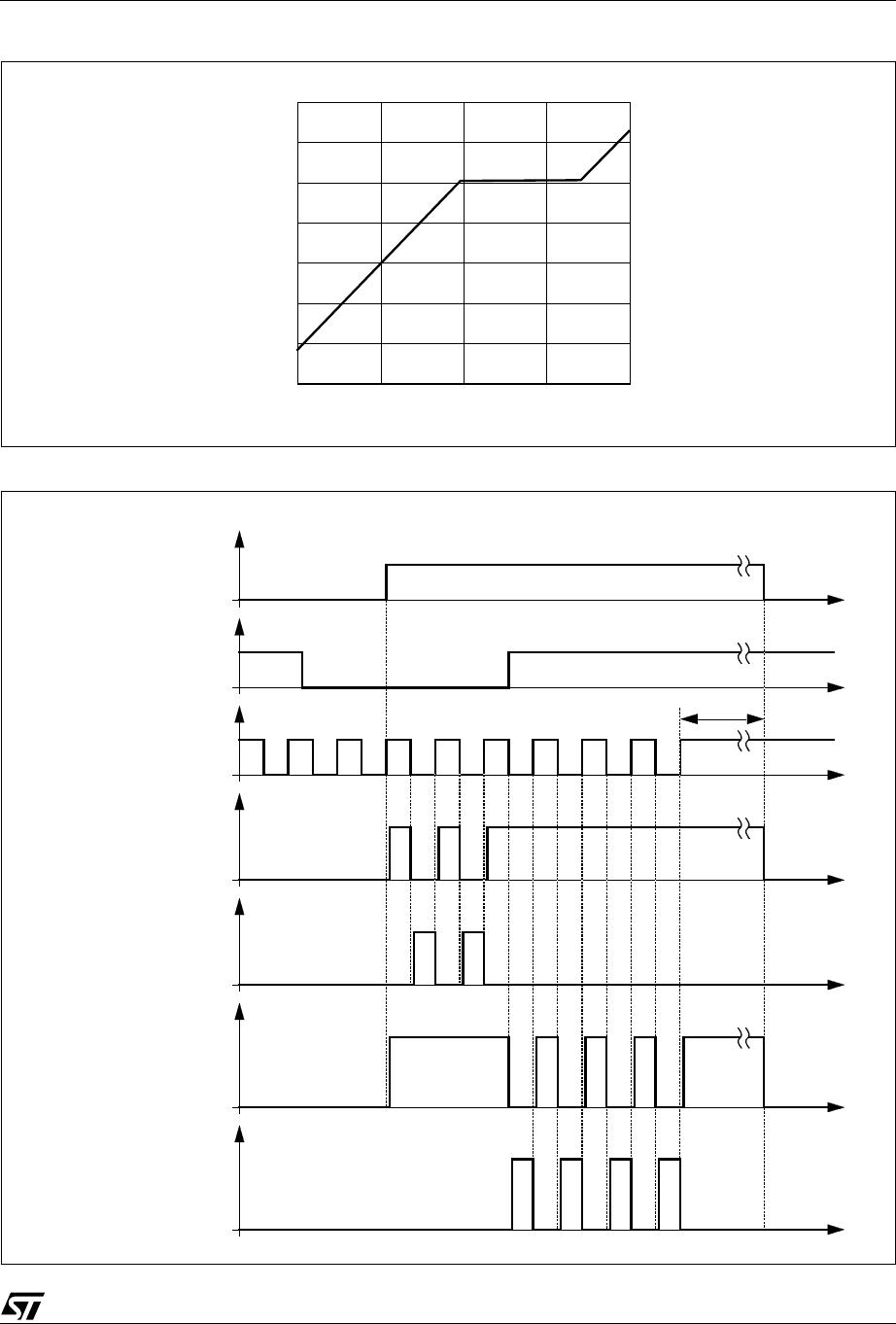
t
GH1LH
t
GH2LH
Propagation delay time including
cross conduction protection time
t
CCP
Fig. 2
V
VS
= 13.5V
V
S1
= V
S2
=0
C
CBX
= 0.1µF
C
PR
= 150pF;
R
PR
= 10k;
5)
0.7 1 1.3 µs
t
GH1HL
t
GH2HL
Propagation delay time 500 ns
t
GL1LH
t
GL2LH
Propagation delay time Fig. 2
V
VS
= 13.5V
V
S1
= V
S2
=0
C
CBX
= 0.1µF
R
PR
= 10k
500 ns
t
GL1LH
t
GL2LH
Propagation delay time including
cross conduction protection time
t
CCP
Fig. 2
V
VS
= 13.5V
V
S1
= V
S2
=0
C
CBX
= 0.1µF
C
PR
= 150pF;
R
PR
= 10k;
5)
0.7 1 1.3 µs
t
GL1HL
t
GL2HL
Propagation delay time 500 ns
t
GH1r
t
GH2r
Rise time Fig. 2
V
VS
= 13.5V
V
S1
= V
S2
=0
C
CBX
= 0.1µF
C
GHX
= 4.7nF
C
GLX
= 4.7nF
R
PR
= 10k;
1µs
t
GH1f
t
GH2f
Fall time 1µs
t
GL1r
t
GL2r
Rise time 1µs
t
GL1f
t
GL2f
Fall time 1µs
Short Circuit Detection
V
S1TH
V
S2TH
Threshold voltage 4 V
t
SCd
Detection time 5 10 15 µs
Step up converter (ST) (5.2V V
VS
< 10V)
V
STH
ST disable HIGH threshold 10 V
V
STh
ST disable threshold hysteresis
voltage
2)
12V
R
DSON
Open drain ON resistance
V
VS
= 5.2V;
I
ST
= 50mA
20
f
ST
Clock frequency 50 100 149 kHz
2. not tested in production: guaranteed by design and verified in characterization
5. tested with differed values in production but guaranteed by design and verified in characterization
Table 5.
Electrical Characteristcs
(continued)
(8V < V
VS
< 20V, V
EN
= HIGH, -40°C
T
J
150°C, unless otherwise specified. The voltages are refered to
GND and currents are assumed positive, when current flows into the pin
Symbol Parameter Test Condition Min. Typ. Max. Unit