9TCS1085
MOBILE ACCESS™—CLOCK SYNTHESIZER, TEMPERATURE SENSOR, & PWM FAN CONTROLLER FOR PORTABLE DEVICES
IDT®
MOBILE ACCESS™—CLOCK SYNTHESIZER, TEMPERATURE SENSOR, & PWM FAN CONTROLLER FOR PORTABLE DEVICES 31
9TCS1085 REV 0.7 012012
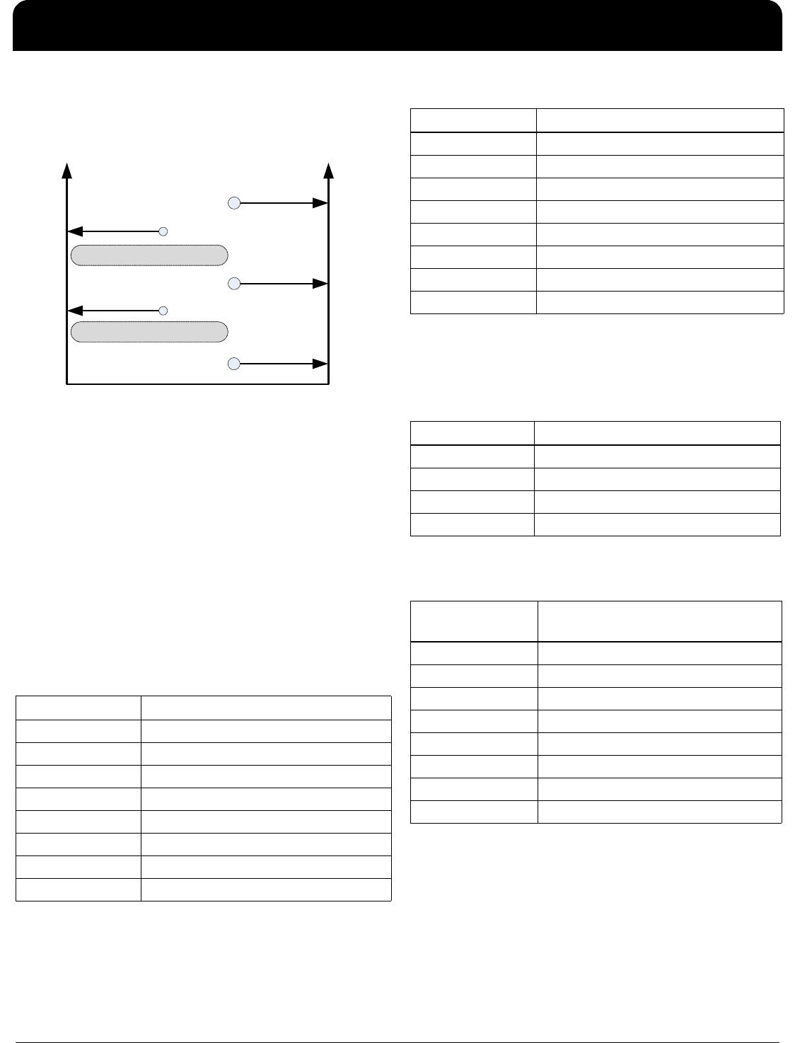
Example of Thermal Trigger Mode Setup
The figure below shows how the programmable thresholds
relate to the fan speed settings.
From the figure above, it can be seen that the fan speed will
adjust between the tachometer settings TACH_S1 and
TACH_S2 given the temperature from the thermal sensor.
The temperature thresholds are set by TH_FAN and
TL_FAN along with the temperature hysteresis, T_HYS. In
this mode, the fan will have active fault condition monitoring
along with fan spin-up control. The rate at which the fan will
speed up or slow down, going from one TACH setting to the
other, can be programmed by the user. Lastly, the fan speed
tolerance can also be selectable via registers.
To set up the fan speed controller in Thermal Trigger Mode,
the following registers will need to be programmed.
(1) Temperature Thresholds:
a. TL_FAN - byte[28], bit[6:0] (default 127°C)
b. TH_FAN - byte[29], bit[6:0] (default 127°C)
To set TL_FAN and TH_FAN a logic "1" is written into the
proper register. For example, to get 70°C, a "1" would be
written for Bit[6], Bit[2], and Bit[1].
(2) Temperature Hysteresis, T_HYS, byte[27], bit[1:0]:
(3) Tachometer Targets:
a. TACH_S1 - byte[32], bit[7:0] and byte[33], bit[7:3]
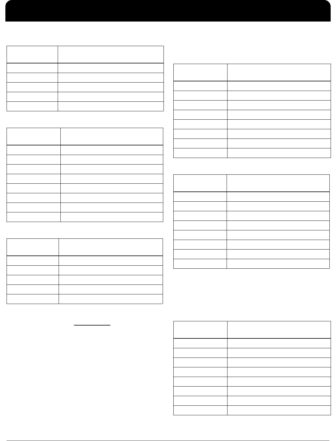
Byte[28], Bit[7:0] Logic "1", Selects Temp Threshold
Bit[7]
Bit[6] 64°C
Bit[5] 32°C
Bit[4] 16°C
Bit[3] 8°C
Bit[2] 4°C
Bit[1] 2°C
Bit[0] 1°C
TempSenser Temperature
Fan Speed
Thermal Hysteresis
Thermal Hysteresis
TACH_S2
TACH_S1
FAN OFF
TH_FAN
TL_FAN
Byte[29], Bit[7:0] Logic "1", Selects Temp Threshold
Bit[7]
Bit[6] 64°C
Bit[5] 32°C
Bit[4] 16°C
Bit[3] 8°C
Bit[2] 4°C
Bit[1] 2°C
Bit[0] 1°C
Byte[27], bit[1:0] Temperature Threshold Hysteresis
[00] 2°C
[01] 5°C
[10] 10°C
[11] (default) 15°C
Byte[32], bit[7:0] Logic "1" selects Tachometer
Reading
Bit[7] 4096
Bit[6] 2048
Bit[5] 1024
Bit[4] 512
Bit[3] 256
Bit[2] 128
Bit[1] 64
Bit[0] 32
9TCS1085
MOBILE ACCESS™—CLOCK SYNTHESIZER, TEMPERATURE SENSOR, & PWM FAN CONTROLLER FOR PORTABLE DEVICES
IDT®
MOBILE ACCESS™—CLOCK SYNTHESIZER, TEMPERATURE SENSOR, & PWM FAN CONTROLLER FOR PORTABLE DEVICES 32
9TCS1085 REV 0.7 012012
b. TACH_S2 - byte[34], bit[7:0] and byte[35], bit[7:3]
The TACH_S1/S2 is set using the following RPM formula:
where: RPM - fan revolution per minute
F
sample
- 25kHz sample internal clock sample rate
TACH_Reading - user programmable registers Byte[32]
through Byte[35]
(4) To Set the minimum and maximum fan speed, use
the RPM formula, “Formula 1”.
a. TACH_MIN - byte[31], bit[7:0]
b. TACH_MAX - byte[30, bit[7:0]
(5) To adjust the rate at which the fan speed will
transition from one TACH setting to the other, the RPM
equation, “Formula 1” is again applied to determine the
incremental or decremental fan speed step size.
Tachometer PWM Step Control - byte[36], bit[7:0]
Byte[33],
bit[7:3]
Logic "1" selects Tachometer
Reading
Bit[7] 16
Bit[6] 8
Bit[5] 4
Bit[4] 2
Bit[3] 1
Byte[34], bit[7:0] Logic "1" selects Tachometer
Reading
Bit[7] 4096
Bit[6] 2048
Bit[5] 1024
Bit[4] 512
Bit[3] 256
Bit[2] 128
Bit[1] 64
Bit[0] 32
Byte[35], bit[7:3] Logic "1" selects Tachometer
Reading
Bit[7] 16
Bit[6] 8
Bit[5] 4
Bit[4 2
Bit[3] 1
60
_Re
2
sample
TACH ading
RPM F ×
(Formula 1)
Byte[31], bit[7:0] Logic "1" selects Tachometer
Reading
Bit[7] 512
Bit[6] 256
Bit[5] 128
Bit[4] 64
Bit[3] 32
Bit[2] 16
Bit[1] 8
Bit[0] 4
Byte[30], bit[7:0] Logic "1" selects Tachometer
Reading
Bit[7] 4096
Bit[6] 2048
Bit[5] 1024
Bit[4] 512
Bit[3] 256
Bit[2] 128
Bit[1] 64
Bit[0] 32
Byte[36], bit[7:0] Logic "1" selects Tachometer
Reading
Bit[7] 128
Bit[6] 64
Bit[5] 32
Bit[4] 16
Bit[3] 8
Bit[2] 4
Bit[1] 2
Bit[0] 1
9TCS1085
MOBILE ACCESS™—CLOCK SYNTHESIZER, TEMPERATURE SENSOR, & PWM FAN CONTROLLER FOR PORTABLE DEVICES
IDT®
MOBILE ACCESS™—CLOCK SYNTHESIZER, TEMPERATURE SENSOR, & PWM FAN CONTROLLER FOR PORTABLE DEVICES 33
9TCS1085 REV 0.7 012012
Spin-up
In this mode the fan controller will also have spin-up control
capabilities. At any time the fan attempts to go from a zero
RPM to a higher fan speed, the fan will always go through
the proper spin-up routine. The time allotted for fan spin-up
as well as the spin-up PWM duty cycle can be adjusted via
registers by writing byte[25], bit[7:3] as follows:
Spin-up Time - byte[25], bit[7:6]
Spin-up PWM duty cycle - byte[25], bit[5:3]
Dynamic PWM Mode
The 9TCS1085 in this mode will be directed by the system
via registers as to the target RPM by which the fan speed
should be running. The system will read a temperature
sensor along with the fan tachometer information and make
the determination as to what the nominal fan speed should
be. This information is fed back to the 9TCS1085 via
register writes. 9TCS1085 will comply and attempt to run
the fan at the requested speed.
To put the 9TCS1085 in Dynamic PWM mode register
byte[24], bit[7:6] = [10]
The system will poll byte[22], bit[7:0], and byte[23], bit[4:0]
for the TACH reading which will correlate to the current fan
speed by the RPM equation, “Formula 1”.
The system can read the temperature sensor diodes from
the 9TCS1085 or from any sensor available to the system to
determine the necessary adjustments to the fan speed.
Byte[25], bit[7:6] Spin-up Time
Bit[7:6] = [00] 250msec
Bit[7:6] = [01] (default) 500msec
Bit[7:6] = [10] 1sec
Bit[7:6] = [11] 2sec
Byte[25], bit[5:3] Spin-up PWM duty cycle
Bit[5:3] = [000] 30%
Bit[5:3] = [001] 35%
Bit[5:3] = [010] 40%
Bit[5:3] = [011] 45%
Bit[5:3] = [100] 50%
Bit[5:3] = [101] 55%
Bit[5:3] = [110] (default) 60%
Bit[5:3] = [111] 65%
Byte[22], bit[7:0] Logic "1" selects Tachometer
Reading
Bit[7] 128
Bit[6] 64
Bit[5] 32
Bit[4] 16
Bit[3] 8
Bit[2] 4
Bit[1] 2
Bit[0] 1
Byte[23], bit[4:0] Logic "1" selects Tachometer
Reading
Bit[7] 4096
Bit[6] 2048
Bit[5] 1024
Bit[4] 512
Bit[3] 256

9TCS1085BNLG

Mfr. #:
Manufacturer:
IDT
Description:
Clock Synthesizer / Jitter Cleaner PLL THERMAL SENSOR AND FAN CONTROLLER
Lifecycle:
New from this manufacturer.
Delivery:
DHL FedEx Ups TNT EMS
Payment:
T/T Paypal Visa MoneyGram Western Union

Products related to this Datasheet