12-OUTPUT DB1200ZL 10 REVISION J 05/25/16
9ZXL1231 DATASHEET
Electrical Characteristics–Phase Jitter Parameters
T
AMB
= T
COM
or T
IND
, unless noted., Supply Voltages per normal operation conditions, See Test Loads for Loading Conditions
PARAMETER SYMBOL CONDITIONS MIN TYP MAX IND.LIMIT UNITS Notes
t
jp
hPCIeG1
PCIe Gen 1 34 45.1 86 ps (p-p) 1,2,3
PCIe Gen 2 Lo Band
10kHz < f < 1.5MHz
1.2 1.43 3
ps
(rms)
1,2
PCIe Gen 2 High Band
1.5MHz < f < Nyquist (50MHz)
2.2 2.63
3.1
ps
(rms)
1,2
t
jphPCIeG3
PCIe Gen 3
(PLL BW of 2-4MHz, CDR = 10MHz)
0.5 0.59
1
ps
(rms)
1,2,4
QPI & SMI
(100MHz or 133MHz, 4.8Gb/s, 6.4Gb/s 12UI)
0.24 0.32 0.5
ps
(rms)
1,4
QPI & SMI
(100MHz, 8.0Gb/s, 12UI)
0.14 0.23 0.3
ps
(rms)
1,4
QPI & SMI
(100MHz, 9.6Gb/s, 12UI)
0.12 0.18 0.2
ps
(rms)
1,4
t
jp
hPCIeG1
PCIe Gen 1 3.7 5.1 n/a ps (p-p) 1,2,3
PCIe Gen 2 Lo Band
10kHz < f < 1.5MHz
0.1 0.2 n/a
ps
(rms)
1,2,5
PCIe Gen 2 High Band
1.5MHz < f < Nyquist (50MHz)
0.4 0.5 n/a
ps
(rms)
1,2,5
t
jphPCIeG3
PCIe Gen 3
(PLL BW of 2-4 or 2-5 MHz, CDR = 10MHz)
0.0
0.1 n/a
ps
(rms)
1,2,4,5
QPI & SMI
(100MHz or 133MHz, 4.8Gb/s, 6.4Gb/s 12UI)
0.14 0.2 n/a
ps
(rms)
1,4,5
QPI & SMI
(100MHz, 8.0Gb/s, 12UI)
0.00 0.01 n/a
ps
(rms)
1,4,5
QPI & SMI
(100MHz, 9.6Gb/s, 12UI)
0.00 0.01 n/a
ps
(rms)
1,4,5
1
Applies to all outputs.
5
For RMS figures, additive jitter is calculated by solving the following equation: Additive jitter = SQRT[(total jittter)^2 - (input jitter)^2]
2
See htt
p
://www.
p
cisi
g
.com for com
p
lete s
p
ecs
3
Sam
p
le size of at least 100K c
y
cles. This fi
g
ures extra
p
olates to 108
p
s
p
k-
p
k @ 1M c
y
cles for a BER of 1-12.
4
Calculated from Intel-supplied Clock Jitter Tool v 1.6.3
Phase Jitter, PLL Mode
t
jphPCIeG2
t
jphQPI_SMI
Additive Phase Jitter,
Bypass mode
t
jphPCIeG2
t
jphQPI_SMI
REVISION J 05/25/16 11 12-OUTPUT DB1200ZL
9ZXL1231 DATASHEET
Clock Periods–Differential Outputs with Spread Spectrum Disabled
Clock Periods–Differential Outputs with Spread Spectrum Enabled
1 Clock 1us 0.1s 0.1s 0.1s 1us 1 Clock
-c2c jitter
AbsPer
Min
-SSC
Short-Term
Average
Min
- ppm
Long-Term
Average
Min
0 ppm
Period
Nominal
+ ppm
Long-Term
Average
Max
+SSC
Short-Term
Average
Ma
x
+c2c jitter
AbsPer
Max
100.00 9.94900 9.99900 10.00000 10.00100 10.05100 ns
133.33 7.44925 7.49925 7.50000 7.50075 7.55075 ns
DIF
Measurement Window
UnitsSSC OFF
Center
Freq.
MHz
1 Clock 1us 0.1s 0.1s 0.1s 1us 1 Clock
-c2c jitter
AbsPer
Min
-SSC
Short-Term
Average
Min
- ppm
Long-Term
Average
Min
0 ppm
Period
Nominal
+ ppm
Long-Term
Average
Max
+SSC
Short-Term
Average
Max
+c2c jitter
AbsPer
Max
99.75 9.94906 9.99906 10.02406 10.02506 10.02607 10.05107 10.10107 ns 1,2,3
133.00 7.44930 7.49930 7.51805 7.51880 7.51955 7.53830 7.58830 ns 1,2,4
Notes:
1
Guaranteed by desi
g
n and characterization, not 100% tested in production.
3
Driven by SRC output of main clock, 100 MHz PLL Mode or Bypass mode
4
Driven by CPU output of main clock, 133 MHz PLL Mode or Bypass mode
2
All Long Term Accuracy specifications are guaranteed with the assumption that the input clock complies with CK420BQ/CK410B+
accuracy requirements (+/-100ppm). The 9ZXL1231 itself does not contribute to ppm error.
DIF
Measurement Window
UnitsSSC ON
Center
Freq.
MHz
Notes
Differential Output Terminations
DIF Zo (
)Rs (
)
100 33
85 27
85ohm Differential Zo
Low-Power
HCSL-
Compatible
Output buffer
9ZXL Differential Test Loads
Rs
Rs
2pF 2pF
10 inches
12-OUTPUT DB1200ZL 12 REVISION J 05/25/16
9ZXL1231 DATASHEET
General SMBus Serial Interface Information for 9ZXL1231
How to Write
Controller (host) sends a start bit
Controller (host) sends the write address
IDT clock will acknowledge
Controller (host) sends the beginning byte location = N
IDT clock will acknowledge
Controller (host) sends the byte count = X
IDT clock will acknowledge
Controller (host) starts sending Byte N through Byte
N+X-1
IDT clock will acknowledge each byte one at a time
Controller (host) sends a Stop bit
How to Read
Controller (host) will send a start bit
Controller (host) sends the write address
IDT clock will acknowledge
Controller (host) sends the beginning byte location = N
IDT clock will acknowledge
Controller (host) will send a separate start bit
Controller (host) sends the read address
IDT clock will acknowledge
IDT clock will send the data byte count = X
IDT clock sends Byte N+X-1
IDT clock sends Byte 0 through Byte X (if X
(H)
was
written to Byte 8)
Controller (host) will need to acknowledge each byte
Controller (host) will send a not acknowledge bit
Controller (host) will send a stop bit
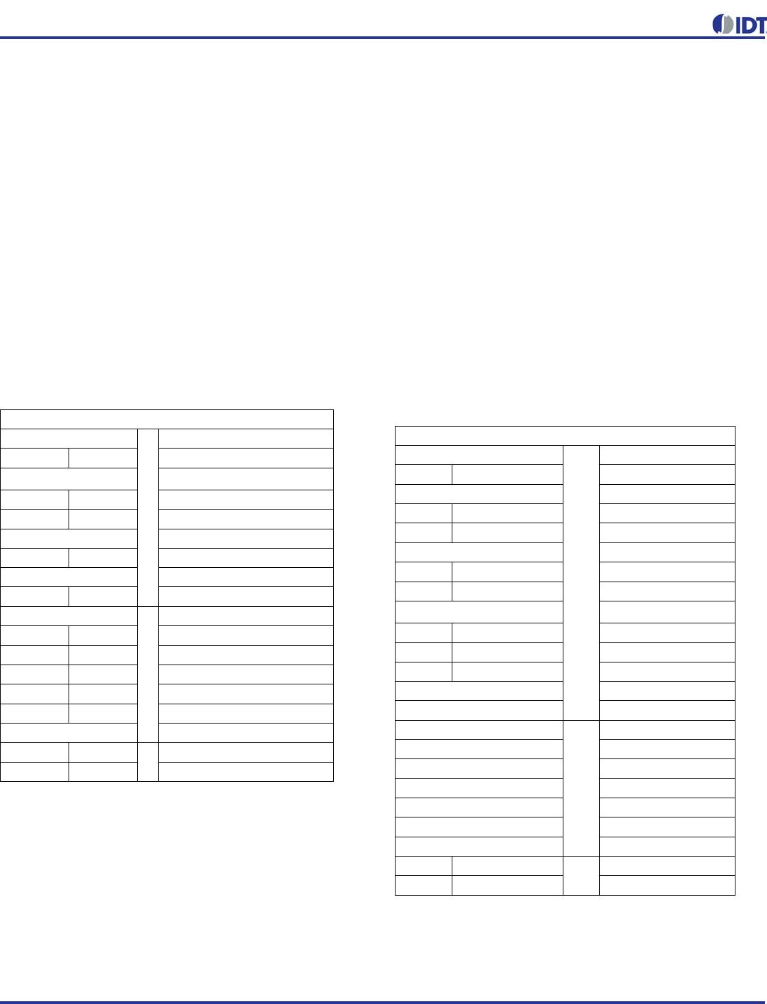
Index Block Write Operation
Controller (Host) IDT (Slave/Receiver)
TstarT bit
Slave Address
WR WRite
ACK
Beginning Byte = N
ACK
Data Byte Count = X
ACK
Beginning Byte N
X Byte
ACK
O
OO
OO
O
Byte N + X - 1
ACK
PstoP bit
Index Block Read Operation
Controller (Host) IDT (Slave/Receiver)
TstarT bit
Slave Address
WR WRite
ACK
Beginning Byte = N
ACK
RT Repeat starT
Slave Address
RD ReaD
ACK
Data Byte Count=X
ACK
X Byte
Beginning Byte N
ACK
O
OO
OO
O
Byte N + X - 1
N Not acknowledge
PstoP bit

9ZXL1231AKLFT

Mfr. #:
Manufacturer:
IDT
Description:
Clock Buffer HIGH PERF. ZDB - LOW POWER
Lifecycle:
New from this manufacturer.
Delivery:
DHL FedEx Ups TNT EMS
Payment:
T/T Paypal Visa MoneyGram Western Union

Products related to this Datasheet