83054I-01 Datasheet
©2015 Integrated Device Technology, Inc December 15, 20157
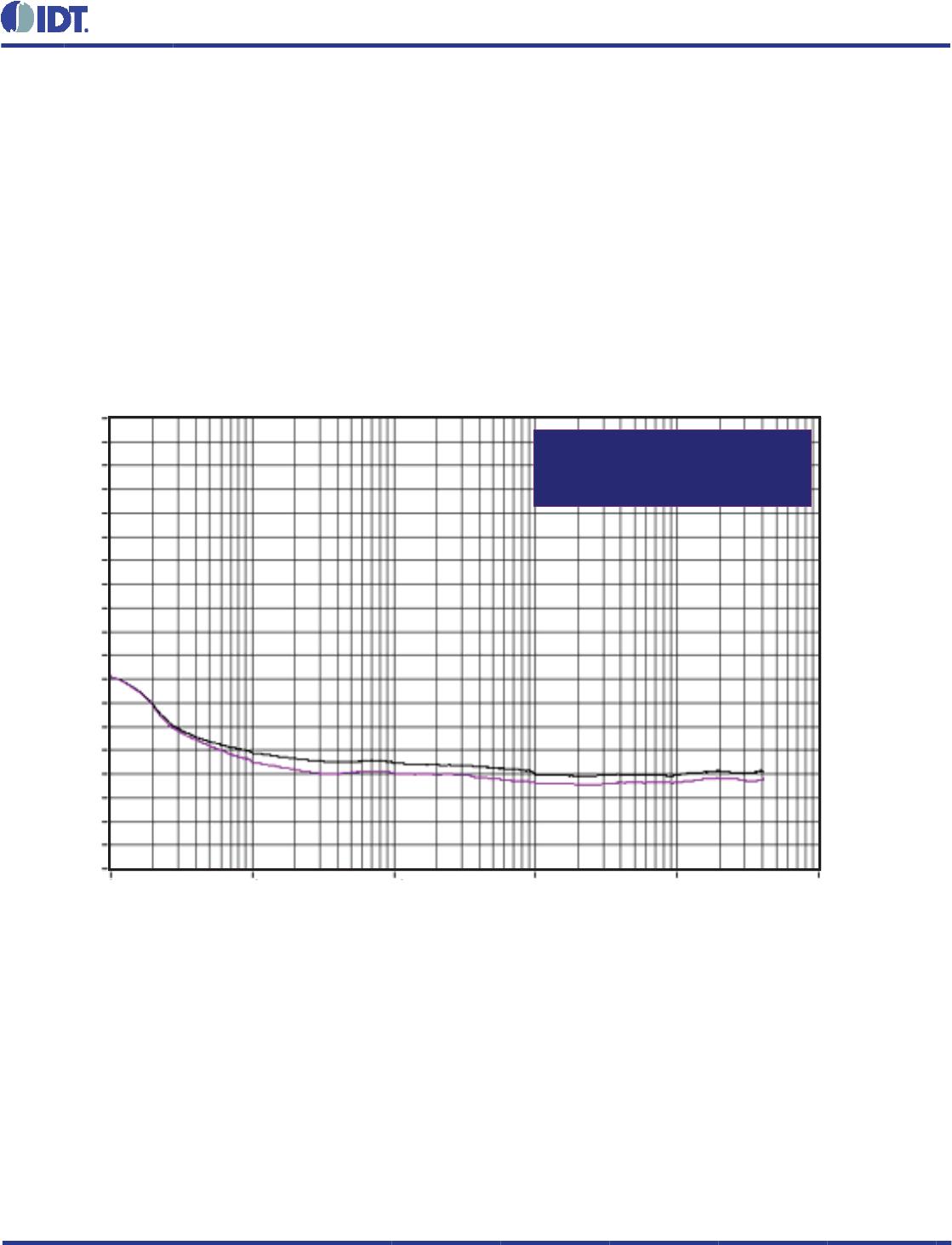
ADDITIVE PHASE JITTER
Additive Phase Jitter (Random)
at 155.52MHz (12kHz - 20MHz)
= 0.18ps (typical)
0
-10
-20
-30
-40
-50
-60
-70
-80
-90
-100
-110
-120
-130
-140
-150
-160
-170
-180
-190
1k 10k 100k 1M 10M 100M
The spectral purity in a band at a specifi c offset from the fundamental
compared to the power of the fundamental is called the dBc Phase
Noise. This value is normally expressed using a Phase noise plot
and is most often the specifi ed plot in many applications. Phase
noise is defi ned as the ratio of the noise power present in a 1Hz
band at a specifi ed offset from the fundamental frequency to the
power value of the fundamental. This ratio is expressed in decibels
As with most timing specifi cations, phase noise measurements has
issues relating to the limitations of the equipment. Often the noise
fl oor of the equipment is higher than the noise fl oor of the device.
(dBm) or a ratio of the power in the 1Hz band to the power in the
fundamental. When the required offset is specifi ed, the phase noise
is called a dBc value, which simply means dBm at a specifi ed offset
from the fundamental. By investigating jitter in the frequency domain,
we get a better understanding of its effects on the desired application
over the entire time record of the signal. It is mathematically possible
to calculate an expected bit error rate given a phase noise plot.
This is illustrated above. The device meets the noise fl oor of what
is shown, but can actually be lower. The phase noise is dependent
on the input source and measurement equipment.
OFFSET FROM CARRIER FREQUENCY (HZ)
SSB PHASE NOISE dBc/HZ

