MAX6698
channel 1. The series resistance cancellation function
increases the conversion time for channel 1 by 125ms.
This feature cancels the bulk resistance of the sensor
and any other resistance in series (wire, contact resis-
tance, etc.). The cancellation range is from 0 to 100Ω.
Discrete Remote Diodes
When the remote-sensing diode is a discrete transistor,
its collector and base must be connected together. Table
11 lists examples of discrete transistors that are appropri-
ate for use with the MAX6698. The transistor must be a
small-signal type with a relatively high forward voltage;
otherwise, the A/D input voltage range can be violated.
The forward voltage at the highest expected temperature
must be greater than 0.25V at 10µA, and at the lowest
expected temperature, the forward voltage must be less
than 0.95V at 100µA. Large power transistors must not be
used. Also, ensure that the base resistance is less than
10Ω. Tight specifications for forward current gain (50 < ß
<150, for example) indicate that the manufacturer has
good process controls and that the devices have consis-
tent V
BE
characteristics. Manufacturers of discrete tran-
sistors do not normally specify or guarantee ideality
factor. This is normally not a problem since good-quality
discrete transistors tend to have ideality factors that fall
within a relatively narrow range. We have observed varia-
tions in remote temperature readings of less than ±2°C
with a variety of discrete transistors. Still, it is good design
practice to verify good consistency of temperature read-
ings with several discrete transistors from any manufac-
turer under consideration.
Unused Diode Channels
If one or more of the remote diode channels is not need-
ed, the DXP and DXN inputs for that channel should
either be unconnected, or the DXP input should be con-
nected to V
CC
. The status register indicates a diode
"fault" for this channel and the channel is ignored during
the temperature-measurement sequence. It is also good
practice to mask any unused channels immediately upon
power-up by setting the appropriate bits in the
Configuration 2 and Configuration 3 registers. This will
prevent unused channels from causing ALERT# or
OVERT# to assert.
Thermistor Measurements
The MAX6698 can use three external thermistors to
measure temperature. A thermistor’s resistance varies
as a function of temperature. A negative temperature
coefficient (NTC) thermistor can be connected between
the thermistor input and ground, with a series resistor,
REXT_, connected from the thermistor input to VREF.
7-Channel Precision Remote-Diode, Thermistor,
and Local Temperature Monitor
14 ______________________________________________________________________________________
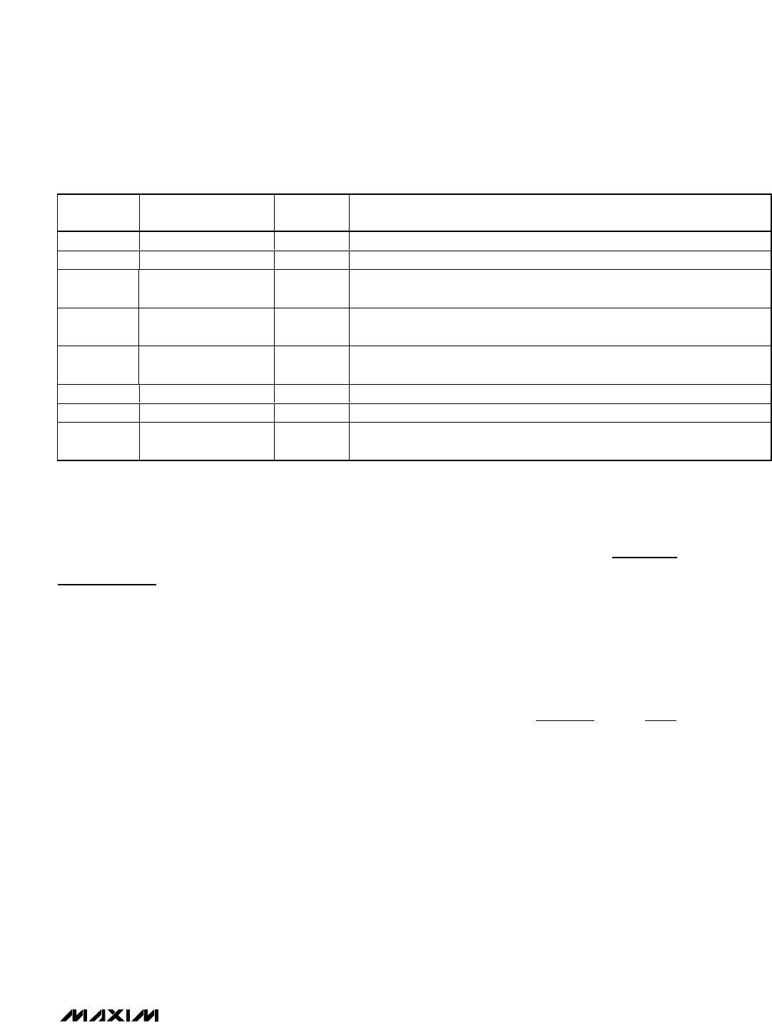
0
Thermistor 1 Alert Bit. This bit is set to logic 1 when the thermistor 1 voltage
exceeds the threshold limit in the thermistor 1 ALERT high-limit register.
2
Remote-Diode 3
ALERT
0
Channel 3 Remote-Diode High-Alert Bit. This bit is set to logic 1 when the
channel 3 remote-diode temperature exceeds the programmed temperature
threshold limit in the remote 3 ALERT high-limit register.
1
Remote-Diode 2
ALERT
0
Channel 2 Remote-Diode High-Alert Bit. This bit is set to logic 1 when the
channel 2 remote-diode temperature exceeds the temperature threshold limit in
the remote 2 ALERT high-limit register.
0
Remote-Diode 1
ALERT
0
Channel 1 Remote-Diode High-Alert Bit. This bit is set to logic 1 when the
channel 1 remote-diode temperature exceeds the temperature threshold limit in
the remote 1 ALERT high-limit register.