2002-2012 Microchip Technology Inc. DS21452C-page 7
TC652/TC653
TABLE 3-3: TEMPERATURE SELECTION
GUIDE
Note: The Bold Type temperature settings are available for ordering.
Contact factory for other temperature selections.
T
L
and T
H
can be selected in 5°C increments. T
H
must
be chosen at least 10°C higher than T
L
. T
L
can range
anywhere from 25°C to 35°C.
As an example, suppose you wanted the fan to run at
40% speed at 25°C or less and go to full speed at
45°C. You would order the part number TC652AEVUA.
As another example, suppose you wanted the fan to
turn on at 30°C and go to full speed at 45°C. You
would order the part number TC653BEVUA.
4.0 TYPICAL APPLICATIONS
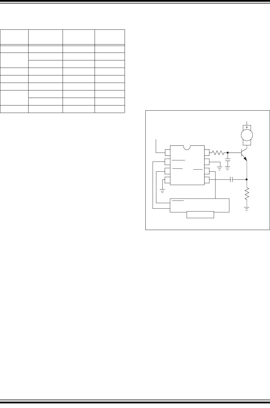
4.1 Reducing Switching Noise
For fans consuming more than 300mA, a slowdown
capacitor (C
SLOW
) is recommended for reducing
switching PWM induced noise (see Figure 4-1). The
value of this capacitor should be 4.7F to 47F,
depending on the fan current consumption.
See Application Note AN771 “Suppressing Acoustic
Noise in PWM Fan Speed Control Systems” for more
information.
FIGURE 4-1: REDUCING SWITCHING
NOISE
Temp.
Range °C
T
L
T
H
Part #
10°C 25 35 AC
30 40 BD
35 45 CE
15°C 25 40 AD
30 45 BE
20°C 25 45 AE
30 50 BF
35 55 CG
30°C 25 55 AG
1
8
2
7
3
6
4
5
V
DD
PWM
GND
T
OVER
NC
GND
GND
+5V V
DD
C
SENSE
C
SLOW
0.01µF
10µF
R
SENSE
2Ω
1kΩ
+12V
TC652
TC653
SHDN
FAULT
GND
µController
DC Fan
400mA
Max.
SHDN Control
Fan Fault Alert
Over-Temp
Alert
-
TC652/TC653
DS21452C-page 8 2002-2012 Microchip Technology Inc.
5.0 TYPICAL CHARACTERISTICS
The graphs and tables provided following this note are a statistical summary based on a limited number of samples
and are provided for informational purposes only. The performance characteristics listed herein are not tested or
guaranteed. In some graphs or tables, the data presented may be outside the specified operating range (e.g., outside
specified power supply range) and therefore outside the warranted range.
90
80
70
60
50
40
30
20
10
0
-50
0
0
246 810
12
14
16
18 20
25
-25
50
75 100 125 150
TEMPERATURE (˚C)
I
DD
vs. Temperature
I
DD
(µA)
3.0
2.5
2.0
1.5
1.0
0.5
0.0
T
L
T
1
T
2
T
3
T
4
T
H
T
THRESHOLD
Temp Accuracy vs. V
TH
TEMP ACCURACY (˚C)
V
DD
– V
OH
(V)
I
SOURCE
(mA)
PWM, I
SOURCE
vs. (V
DD
- V
OH
), T
A
= 25˚
C
V
DD
= 2.8V
V
DD
= 5.5V
V
DD
=
2.7V
V
DD
=
5.6V
V
DD
=
5.6V
V
DD
=
2.7V
0.0
0.1
0.2
0.3
0.4
0.5
0.6
0.7
0.8
0.9
1.0
0.0
0.1
0.2
0.3
0.4
0.5
0.6
0.7
0.8
0.9
1.0
0
123 4 5
6
7
8
910
V
OL
(mV)
I
SINK
(mA)
PWM, I
SINK
vs. V
OL
, T
A
= 25˚C
V
DD
= 2.8V
V
DD
= 5.5V
0
50
100
150
200
250
300
350
400
450
500
V
DD
– V
OH
(V)
I
SOURCE
(mA)
T
OVER
, I
SOURCE
vs. (V
DD
- V
OH
), T
A
= 25˚C
V
DD
= 2.8V
V
DD
= 5.5V
0
123 4 5
6
7
8
910
0.0
0.1
0.2
0.3
0.4
0.5
0.6
0.7
0.8
0.9
1.0
V
DD
– V
OH
(V)
I
SOURCE
(mA)
FAULT, I
SOURCE
vs. (V
DD
- V
OH
), T
A
= 25˚C
V
DD
= 2.8V
V
DD
= 5.5V
0
123 4 5
6
7
8
910
0
123 4 5
6
7
8
910
1.0 1.5 2.0 2.5
3.0
3.5 4.0 5.04.50.5
5.0
5.0
5.0
0.0
0.0
0.0
V
OL
(mV)
I
SINK
(mA)
500msec/Div
FAULT, I
SINK
vs. V
OL
, T
A
= 25˚C
V
DD
= 2.8V
V
DD
= 5.5V
0
50
100
150
200
250
300
350
400
450
500
TC652/3, Fan is Running
SHDN is Connected to V
DD
, T
A
= 25˚C
Start-Up Time
0
V
DD
PWM
FAULT
23 4 5
6
78 1091
5.0
5.0
5.0
0.0
0.0
0.0
1sec/Div
TC653, Fan is Not Running
SHDN is Connected to V
DD
, T
A
= 25˚C
0
V
DD
PWM
FAULT
2002-2012 Microchip Technology Inc. DS21452C-page 9
TC652/TC653
6.0 PACKAGING INFORMATION
6.1 Package Marking Information
Package marking data not available at this time.
6.2 Taping Form

TC652ACVUATR

Mfr. #:
Manufacturer:
Microchip Technology
Description:
Motor / Motion / Ignition Controllers & Drivers W/ Fan Flt & Over T
Lifecycle:
New from this manufacturer.
Delivery:
DHL FedEx Ups TNT EMS
Payment:
T/T Paypal Visa MoneyGram Western Union