2014 Microchip Technology Inc. Advance Information DS40001751A-page 1
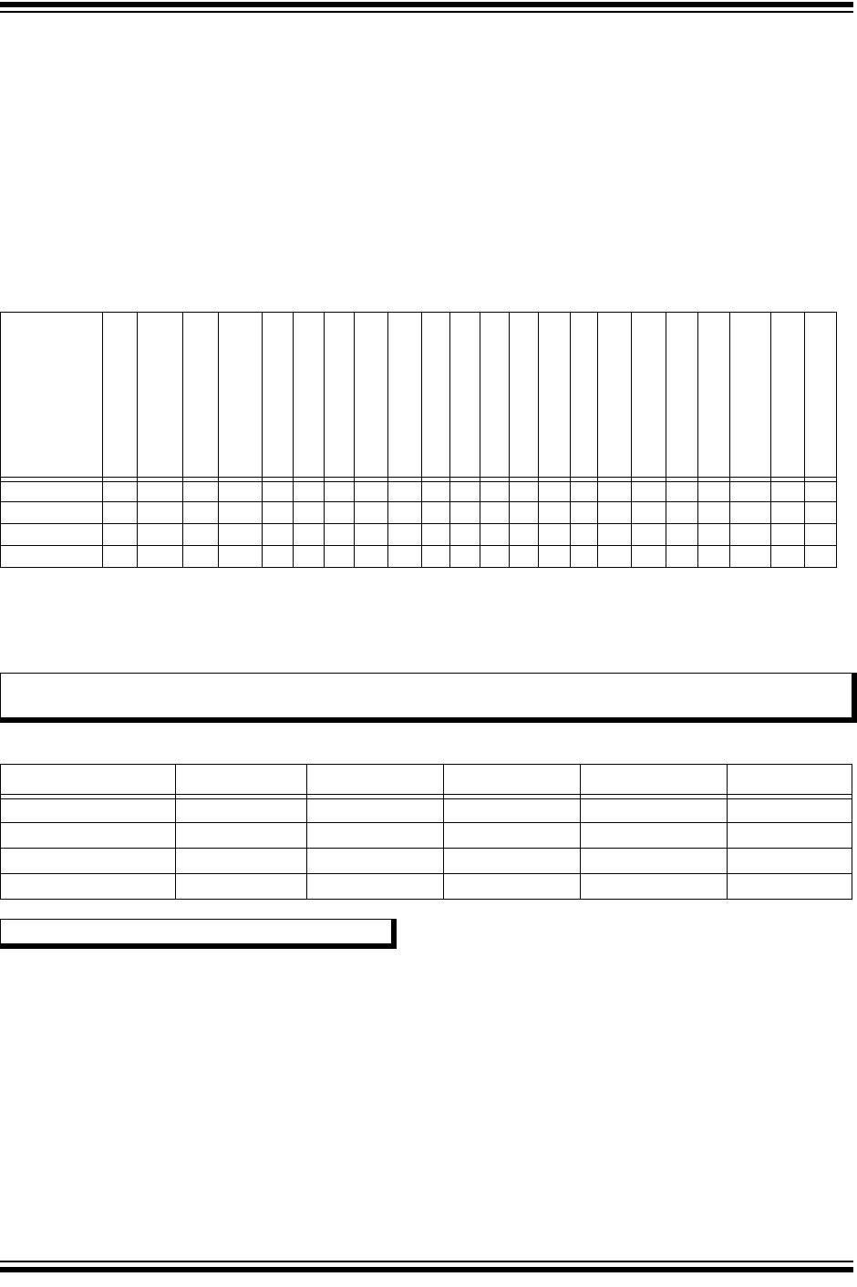
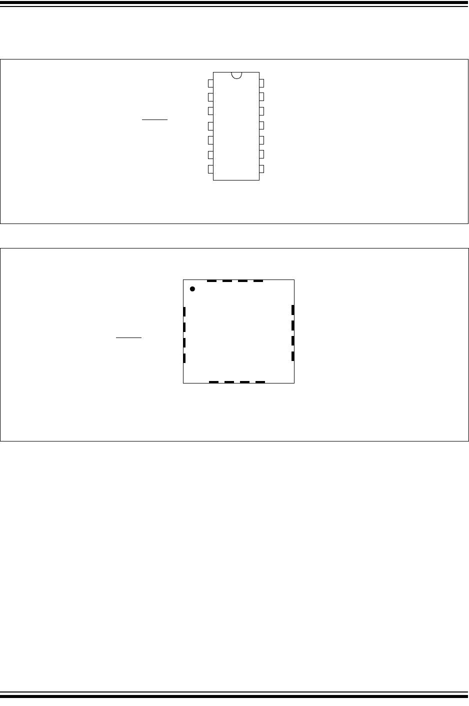
PIC16(L)F1764/5/8/9
Description:
PIC16(L)F176X microcontrollers combine intelligent analog integration with digital peripherals to suit a variety of
functions and end equipment. These 14/20-pin devices provide features like 10-bit A/D, op amps, zero-cross detect,
high current IOs, communication, peripheral pin select and other key peripherals that make this family appealing in
applications looking for design flexibility.
Core Features:
• C Compiler Optimized RISC Architecture
• Only 49 Instructions
• Operating Speed:
- DC – 32 MHz clock input
- 125 ns minimum instruction cycle
• Interrupt Capability
• 16-Level Deep Hardware Stack
• Up to Four 8-Bit Timers
• Up to Three 16-Bit Timers
• Power-on Reset (POR)
• Configurable Power-up Timer (PWRT)
• Brown-out Reset (BOR) with Selectable Trip Point
• Extended Watchdog Timer (EWDT):
- Low-power 31 kHz WDT
- Software-selectable prescaler
- Software-selectable enable
Memory:
• Up to 14 KB Flash Program Memory
• Up to 1024 Bytes Data RAM Memory
• Direct, Indirect and Relative Addressing modes
• High Endurance Flash (HEF)
- 128B of nonvolatile data storage
- 100K Erase/Write cycles
Operating Characteristics:
• Operating Voltage Range:
- 1.8V to 3.6V (PIC16LF176X)
- 2.3V to 5.5V (PIC16F176X)
• Temperature Range:
- Industrial: -40°C to 85°C
- Extended: -40°C to 125°C
eXtreme Low-Power (XLP) Features:
• Sleep mode: 50 nA @ 1.8V, typical
• Watchdog Timer: 500 nA @ 1.8V, typical
• Secondary Oscillator 500 nA @ 32 kHz
• Operating Current:
- 8 uA @ 32 kHz, 1.8V, typical
- 32 uA/MHz @ 1.8V, typical
• Low-Power BOR (LPBOR):
- 200 nA in Sleep
Digital Peripherals:
• Configurable Logic Cell (CLC):
- Up to three CLCs; up to four selected inputs
- Integrated combinational and state logic
• Up to Two Complementary Output Generators
(COG):
- Push-Pull, Full-Bridge and Steering modes
• Up to Two Capture/Compare/PWM (CCP)
modules
• Pulse-Width Modulators (PWM):
- Up to two 10-bit PWMs
- Up to two 16-bit PWMs
• Peripheral Pin Select (PPS):
- Configure any digital pin to output
• Serial Communications:
- Enhanced USART (EUSART)
- SPI, I
2
C™, RS-232, RS-485, LIN compatible
- Auto-Baud Detect, auto-wake-up on start
• Up to 18 I/O Pins:
- Individually programmable pull-ups
- Slew rate control
- Interrupt-on-change with edge-select
• Up to Two Data Signal Modulators (DSM)
Intelligent Analog Peripherals:
• 10-Bit Analog-to-Digital Converter (ADC):
- Up to 12 external channels
- Conversion available during Sleep
• Up to Two Operational Amplifiers (OPA):
- Selectable internal and external channels
- High and low GBWP operating modes
• Up to Four Fast Comparators (COMP):
- Low-Power/High-Speed mode
- Up to five external inverting inputs
- Up to eight external non-inverting inputs
- Fixed Voltage Reference at non-inverting
input(s)
- Comparator outputs externally accessible
• Digital-to-Analog Converters (DAC):
- Up to two 10-bit resolution DACs
- Up to two 5-bit resolution DACs
14/20-Pin, 8-Bit Flash Microcontroller Product Brief