BGU7224 All information provided in this document is subject to legal disclaimers. © NXP Semiconductors N.V. 2014. All rights reserved.
Product data sheet Rev. 2 — 15 December 2014 14 of 20
NXP Semiconductors
BGU7224
2.4 GHz ISM SiGe:C low-noise amplifier MMIC with bypass
11.2 Application circuit
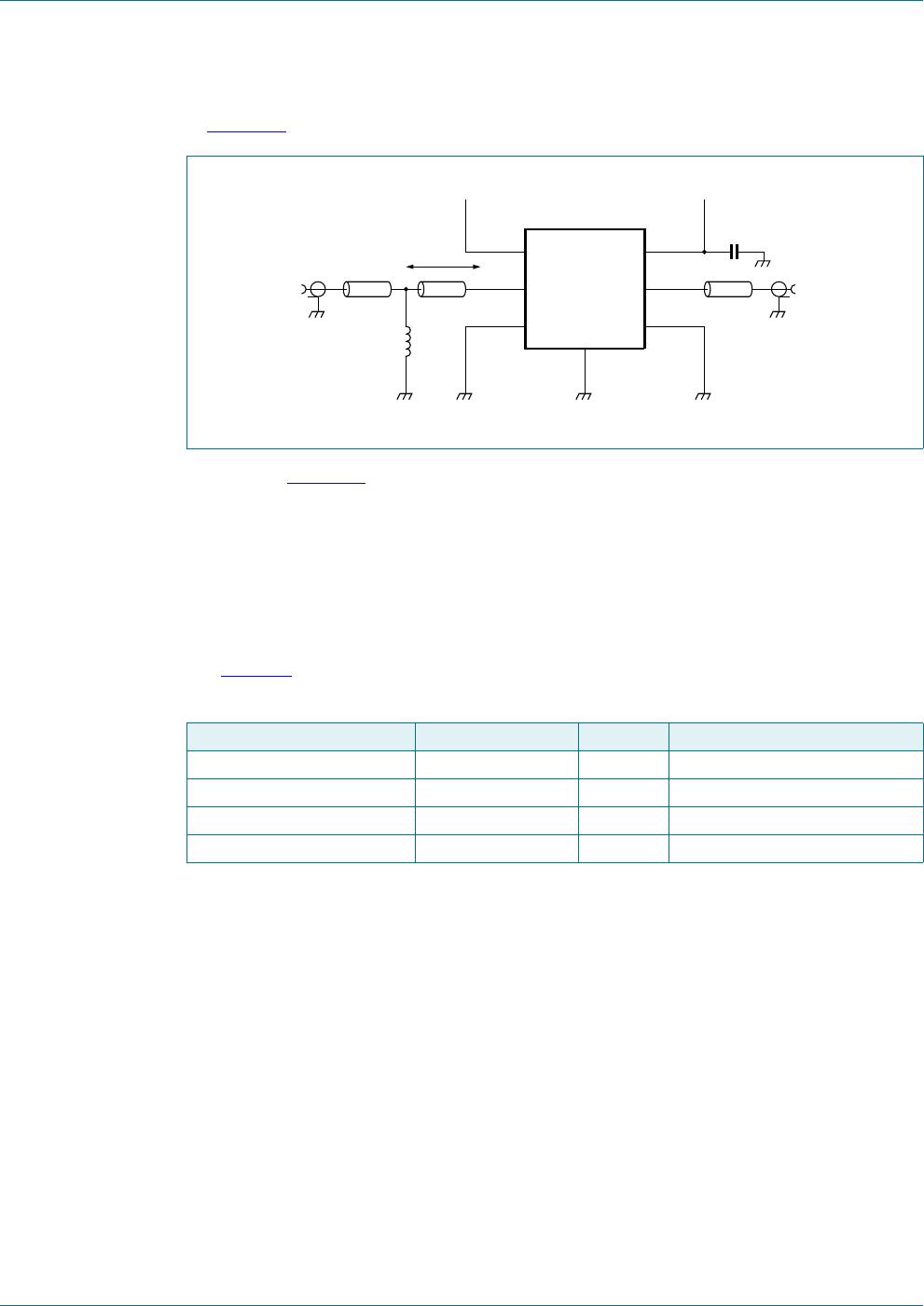
In Figure 33 the application diagram as supplied on the evaluation board is given.
Note that in Figure 33 the schematic for the BGU7224 evaluation board is shown using
only two external components. A DC-decoupling capacitor placed close to V
CC
(pin 6) and
a matching shunt inductor at RF_IN.
The BGU7224 can also be used without the matching inductor at RF_IN. However, in this
case the input return loss will be less than 10 dB (approximately 9 dB) at a frequency of
2.4 GHz.
For more details or information please see application note AN11390.
Fig 33. Evaluation board schematic
Table 10. List of components
See Figure 33 for evaluation board schematic.
Preferred vendors different from the ones listed can be chosen, but be aware that the performance
could be affected.
Component Description Value Remarks
C1 capacitor 4.7 nF Murata GRM155 series
shunt inductor inductor 8.2 nH Murata LQP15 series
RF_IN, RF_OUT SMA connector - Emerson Network Power
V
CC
, LNA gain/bypass 3-pin connector - Molex
*1'
%*8
9
&&
5)B287
*1'
*1'
&
ȍ
ȍ ȍ
VKXQW
LQGXFWRU

