BGU7224 All information provided in this document is subject to legal disclaimers. © NXP Semiconductors N.V. 2014. All rights reserved.
Product data sheet Rev. 2 — 15 December 2014 4 of 20
NXP Semiconductors
BGU7224
2.4 GHz ISM SiGe:C low-noise amplifier MMIC with bypass
7. Thermal characteristics
8. Static characteristics
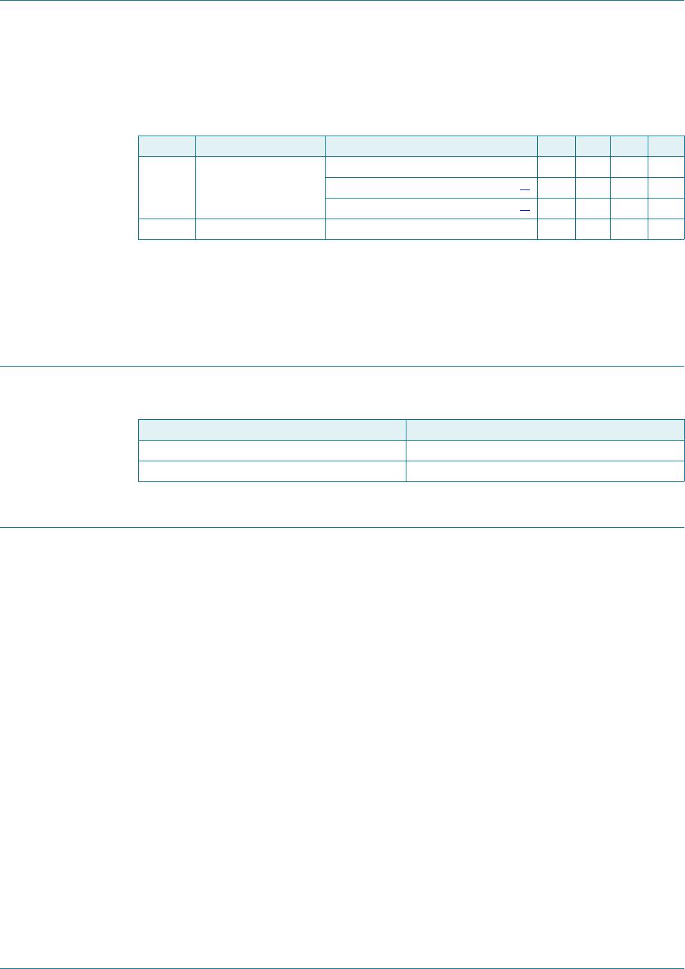
9. Dynamic characteristics
Table 6. Thermal characteristics
Symbol Parameter Conditions Typ Unit
R
th(j-case)
thermal resistance from junction to case 250 K/W
Table 7. Static characteristics
Symbol Parameter Conditions Min Typ Max Unit
V
CC
supply voltage RF input, AC coupled 3.0 3.3 3.6 V
I
CC
supply current P
i
= 30 dBm
gain mode - 13 - mA
bypass mode - 2 - A
I
I(CTRL)
input current on pin CTRL gain mode - 50 - A
T
amb
ambient temperature 40 +25 +85 C
Table 8. Dynamic characteristics
T
amb
=25
C; V
CC
= 3.3 V; Z
S
= Z
L
= 50
; P
i
=
30 dBm unless otherwise specified. All
measurements done on application board (with a DC-decoupling capacitor of 4.7 nF placed close to
V
CC
[pin 6] and a 8.2 nH matching shunt inductor at RF_IN) with SMA connectors as reference
plane.
Symbol Parameter Conditions Min Typ Max Unit
f frequency
[1]
2400 - 2500 MHz
G
p
power gain gain mode
[2]
13 15 17 dB
bypass mode
[2]
- 5.5 - dB
RL
in
input return loss gain mode - 10 - dB
bypass mode - 13 - dB
RL
out
output return loss gain mode - 11 - dB
bypass mode - 13 - dB
ISL isolation gain mode - 22 - dB
G
flat
gain flatness bandwidth across 40 MHz
gain mode - 0.2 - dB
bypass mode - 0.2 - dB
P
i(1dB)
input power at 1 dB
gain compression
gain mode - 3- dBm
IP3
I
input third-order
intercept point
two-tone; 5 MHz spacing
P
i
= 20 dBm; gain mode - 5.5 - dBm
P
i
= 3 dBm; bypass mode - 34 - dBm
NF noise figure gain mode
[2]
-1.0-dB
BGU7224 All information provided in this document is subject to legal disclaimers. © NXP Semiconductors N.V. 2014. All rights reserved.
Product data sheet Rev. 2 — 15 December 2014 5 of 20
NXP Semiconductors
BGU7224
2.4 GHz ISM SiGe:C low-noise amplifier MMIC with bypass
[1] ISM 2.4 GHz (in band).
[2] Printed-Circuit Board (PCB) and connector losses excluded.
[3] measured from 50 % of V
I(CTRL)
control signal to 90% of maximum RF output signal.
[4] measured from 50 % of V
I(CTRL)
control signal to 10% of maximum RF output signal.
10. Gain control
11. Application information
Please contact your local sales representative for more information. Application note
AN11390 is available on the NXP website.
t
sw(G)
gain switch time V
I(CTRL)
= 0 V to 3.3 V
gain mode
[3]
-150-ns
bypass mode
[4]
-20-ns
K Rollett stability factor 0 GHz f 20 GHz; gain mode - > 1 -
Table 8. Dynamic characteristics …continued
T
amb
=25
C; V
CC
= 3.3 V; Z
S
= Z
L
= 50
; P
i
=
30 dBm unless otherwise specified. All
measurements done on application board (with a DC-decoupling capacitor of 4.7 nF placed close to
V
CC
[pin 6] and a 8.2 nH matching shunt inductor at RF_IN) with SMA connectors as reference
plane.
Symbol Parameter Conditions Min Typ Max Unit
Table 9. Gain control (pin CTRL)
T
amb
=25
C; V
CC
= 3.3 V.
V
I(CTRL)
(V) Mode
0.5 bypass
2.5 gain
BGU7224 All information provided in this document is subject to legal disclaimers. © NXP Semiconductors N.V. 2014. All rights reserved.
Product data sheet Rev. 2 — 15 December 2014 6 of 20
NXP Semiconductors
BGU7224
2.4 GHz ISM SiGe:C low-noise amplifier MMIC with bypass
11.1 Graphs
Typical performance measured on the application board.
T
amb
= 25 C; gain mode
(1) V
CC
= V
I(CTRL)
= 3.0 V
(2) V
CC
= V
I(CTRL)
= 3.3 V
(3) V
CC
= V
I(CTRL)
= 3.6 V
T
amb
= 25 C; gain mode
(1) V
CC
= V
I(CTRL)
= 3.0 V
(2) V
CC
= V
I(CTRL)
= 3.3 V
(3) V
CC
= V
I(CTRL)
= 3.6 V
Fig 2. Input reflection coefficient as a function of
frequency at different supply voltages
Fig 3. Input reflection coefficient as a function of
frequency at different supply voltages
T
amb
= 25 C; gain mode
(1) V
CC
= V
I(CTRL)
= 3.0 V
(2) V
CC
= V
I(CTRL)
= 3.3 V
(3) V
CC
= V
I(CTRL)
= 3.6 V
T
amb
= 25 C; gain mode
(1) V
CC
= V
I(CTRL)
= 3.0 V
(2) V
CC
= V
I(CTRL)
= 3.3 V
(3) V
CC
= V
I(CTRL)
= 3.6 V
Fig 4. Forward transmission coefficient as a function
of frequency at different supply voltages
Fig 5. Forward transmission coefficient as a function
of frequency at different supply voltages
DDD
     





I*+]
6

6

G%G%G%



DDD






I*+]
6

6

G%G%G%



DDD
     






I*+]
6

6

G%G%G%



DDD




I*+]
6

6

G%G%G%




BGU7224X

Mfr. #:
Manufacturer:
NXP Semiconductors
Description:
RF Amplifier 2.4 GHz ISM SiGe:C low-noise amp
Lifecycle:
New from this manufacturer.
Delivery:
DHL FedEx Ups TNT EMS
Payment:
T/T Paypal Visa MoneyGram Western Union

Products related to this Datasheet