IDT 89HPES24NT6AG2 Datasheet
16 of 34 December 17, 2013
Figure 5 JTAG AC Timing Waveform
Recommended Operating Temperature
Recommended Operating Supply Voltages — Commercial Temperature
Grade Temperature
Commercial 0C to +70C Ambient
Industrial -40C to +85C Ambient
Table 15 PES24NT6AG2 Operating Temperatures
Symbol Parameter Minimum Typical Maximum Unit
V
DD
CORE Internal logic supply 0.9 1.0 1.1 V
V
DD
I/O I/O supply except for SerDes 3.125 3.3 3.465 V
V
DD
PEA
1
1.
V
DD
PEA and V
DD
PETA should have no more than 25mV
peak-peak
AC power supply noise superimposed on the 1.0V nominal DC
value.
PCI Express Analog Power 0.95 1.0 1.1 V
V
DD
PEHA
2
2.
V
DD
PEHA should have no more than 50mV
peak-peak
AC power supply noise superimposed on the 2.5V nominal DC value.
PCI Express Analog High Power 2.25 2.5 2.75 V
V
DD
PETA
1
PCI Express Transmitter Analog Voltage 0.95 1.0 1.1 V
V
SS
Common ground 0 0 0 V
Table 16 PES24NT6AG2 Operating Voltages — Commercial Temperature
Tpw_16d
Tdz_16cTdo_16c
Thld_16b
Tsu_16b
Thld_16b
Tsu_16b
Tlow_16aTlow_16a
Tper_16a
Thigh_16a
JTAG_TCK
JTAG_TDI
JTAG_TMS
JTAG_TDO
JTAG_TRST_N
IDT 89HPES24NT6AG2 Datasheet
17 of 34 December 17, 2013
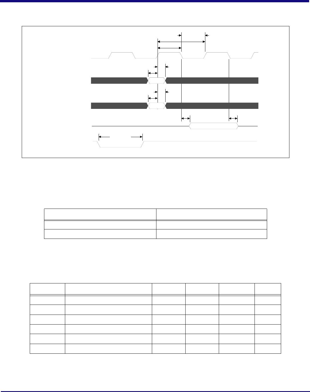
Recommended Operating Supply Voltages — Industrial Temperature
Power-Up/Power-Down Sequence
During power supply ramp-up, V
DD
CORE must remain at least 1.0V below V
DD
I/O at all times. There are no other power-up sequence require-
ments for the various operating supply voltages. The power-down sequence can occur in any order.
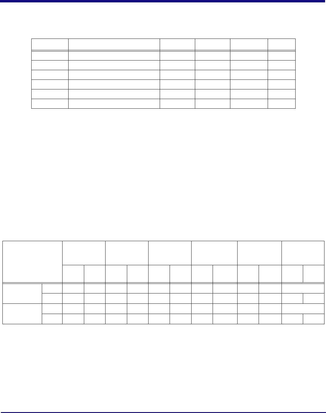
Power Consumption
Typical power is measured under the following conditions: 25°C Ambient, 35% total link usage on all ports, typical voltages defined in Table 16
(and also listed below).
Maximum power is measured under the following conditions: 70°C Ambient, 85% total link usage on all ports, maximum voltages defined in
Table 16 (and also listed below).
Note 1: The above power consumption assumes that all ports are functioning at Gen2 (5.0 GT/S) speeds. Power consumption can be
reduced by turning off unused ports through software or through boot EEPROM. Power savings will occur in V
DD
PEA, V
DD
PEHA, and
V
DD
PETA. Power savings can be estimated as directly proportional to the number of unused ports, since the power consumption of a turned-
off port is close to zero. For example, if 3 ports out of 16 are turned off, then the power savings for each of the above three power rails can be
calculated quite simply as 3/16 multiplied by the power consumption indicated in the above table.
Note 2: Using a port in Gen1 mode (2.5GT/S) results in approximately 18% power savings for each power rail: V
DD
PEA, V
DD
PEHA, and
V
DD
PETA.
Symbol Parameter Minimum Typical Maximum Unit
V
DD
CORE Internal logic supply 0.9 1.0 1.1 V
V
DD
I/O I/O supply except for SerDes 3.125 3.3 3.465 V
V
DD
PEA
1
1.
V
DD
PEA and V
DD
PETA should have no more than 25mV
peak-peak
AC power supply noise superimposed on the 1.0V nominal DC
value.
PCI Express Analog Power 0.95 1.0 1.05 V
V
DD
PEHA
2
2.
V
DD
PEHA should have no more than 50mV
peak-peak
AC power supply noise superimposed on the 2.5V nominal DC value.
PCI Express Analog High Power 2.25 2.5 2.75 V
V
DD
PETA
1
PCI Express Transmitter Analog Voltage 0.95 1.0 1.1 V
V
SS
Common ground 0 0 0 V
Table 17 PES24NT6AG2 Operating Voltages — Industrial Temperature
Number of Active
Lanes per Port
Core Supply
PCIe Analog
Supply
PCIe Analog
High Supply
PCIe
Transmitter
Supply
I/O Supply Total
Typ
1.0V
Max
1.1V
Typ
1.0V
Max
1.1V
Typ
2.5V
Max
2.75V
Typ
1.0V
Max
1.1V
Typ
3.3V
Max
3.465
Typ
Power
Max
Power
x8/x8/x4/x4
(Full Swing)
mA 2260 3400 1343 1471 178 178 516 574 3 5
Watts 2.26 3.74 1.34 1.62 0.45 0.49 0.52 0.63 0.01 0.02 4.58 6.5
x8/x8/x4/x4
(Half Swing)
mA 2260 3400 1155 1265 178 178 268 299 3 5
Watts 2.26 3.74 1.16 1.39 0.45 0.49 0.27 0.33 0.01 .02 4.15 5.97
Table 18 PES24NT6AG2 Power Consumption
IDT 89HPES24NT6AG2 Datasheet
18 of 34 December 17, 2013
Thermal Considerations
This section describes thermal considerations for the PES24NT6AG2 (23mm
2
FCBGA484 package). The data in Table 19 below contains informa-
tion that is relevant to the thermal performance of the PES24NT6AG2 switch.
Note: It is important for the reliability of this device in any user environment that the junction temperature not exceed the T
J(max)
value
specified in Table 19. Consequently, the effective junction to ambient thermal resistance (
JA
) for the worst case scenario must be
maintained below the value determined by the formula:
JA
= (T
J(max)
- T
A(max)
)/P
Given that the values of T
J(max)
, T
A(max)
, and P are known, the value of desired
JA
becomes a known entity to the system designer. How to
achieve the desired
JA
is left up to the board or system designer, but in general, it can be achieved by adding the effects of
JC
(value
provided in Table 19), thermal resistance of the chosen adhesive (
CS
), that of the heat sink (
SA
), amount of airflow, and properties of the
circuit board (number of layers and size of the board). It is strongly recommended that users perform their own thermal analysis for their own
board and system design scenarios.
Symbol Parameter Value Units Conditions
T
J(max)
Junction Temperature 125
o
CMaximum
T
A(max)
Ambient Temperature 70
o
C Maximum for commercial-rated products
85
o
C Maximum for industrial-rated products
JA(effective)
Effective Thermal Resistance, Junction-to-Ambient
15.2
o
C/W Zero air flow
8.5
o
C/W 1 m/S air flow
7.1
o
C/W 2 m/S air flow
JB
Thermal Resistance, Junction-to-Board 3.1
o
C/W
JC
Thermal Resistance, Junction-to-Case 0.15
o
C/W
P Power Dissipation of the Device 6.5 Watts Maximum
Table 19 Thermal Specifications for PES24NT6AG2, 23x23 mm FCBGA484 Package

89H24NT6AG2ZCHLG

Mfr. #:
Manufacturer:
IDT
Description:
PCI Interface IC PCIE SWITCH
Lifecycle:
New from this manufacturer.
Delivery:
DHL FedEx Ups TNT EMS
Payment:
T/T Paypal Visa MoneyGram Western Union