AXL F DI16/1 HS 1H
8610_en_01 PHOENIX CONTACT 7
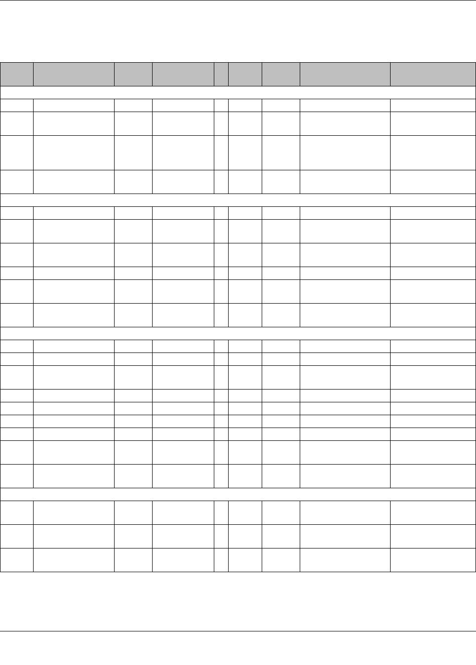
8 Local status and diagnostic indicators
Figure 4 Local status and diagnostic indicators
D
UI
30 3231 33
20 2221 23
10 1211 13
00 0201 03
Designa-
tion
Color Meaning State Description
D Red/yel-
low/green
Diagnostics of local bus communication
Power down OFF Device in (power) reset.
Not connected Red flash-
ing
Device operating, but there is no connection to previous device.
Reset Red ON Application reset
Device operating, but there is still a connection to the previous de-
vice, the application is reset.
Ready Yellow ON Device operating, there is still a connection to the previous device,
but the device has not yet detected a valid cycle after power on.
Connected Yellow
flashing
Valid data cycles have been detected, but the device is (not) yet
part of the current configuration.
Device applica-
tion not active
Green/yel-
low alter-
nating
Valid data cycles are being detected.
The master application set the output data to valid, however, the
slave application has not set the input data to valid as yet.
Active Green
flashing
Device operating, communications within the station is OK.
The master application does not read the input data.
(The connection to the controller has not yet been established, for
example.)
Run Green ON Valid data cycles are being detected. All data is valid
UI Green U
Input
ON Supply of digital input modules present.
OFF Supply of digital input modules not present.
00 ... 03,
10 ... 13,
20 ... 23,
30 ... 33
Yellow Status of the in-
puts
ON Input is set.
OFF Input is not set.
For more information on the meaning of local
diagnostic and status indicators, please refer
to the UMENAXLSYSINST user manual.