12
Implementing Autoreset on the ISL6119
Hot Swap Controller
Abstract
In applications where the cost, complexity or requirement for
a system controller is avoided and an autonomous power
control function is desired, a device that can monitor and
protect against excessive current failures is needed. This
tech brief shows how to implement such an autonomous
controller using the ISL6119HIB. This application works only
with the ‘H’ version of this device. The ‘H’ version refers to
the enable function being asserted upon a high input.
Introduction
The ISL6118, ISL6119 and ISL6121 are all 2.5V to 5V power
supply controllers, each having a different level of current
regulation (CR). The ISL6118 and ISL6119 have 2
independent controllers with CR levels of 0.6A and 1.0A
respectively whereas the ISL6121 is a single supply
controller with a 2A CR level. Each of these devices features
integrated power switch(es) for power control. Each switch is
driven by a constant current source giving a controlled ramp
up of the output voltage. This provides a soft start turn-on
eliminating bus voltage drooping caused by in-rush current
while charging heavy load capacitances. The independent
enabling inputs and fault reporting outputs for each channel
are available and necessary for the autonomous autoreset
application.
The undervoltage (UV) feature prevents turn-on of the
outputs unless the ENABLE pin and VIN are > 2.5V. During
initial turn-on the ISL6119 prevents fault reporting by
blanking the fault signal. Rising and falling outputs are
current-limited voltage ramps so that both the inrush current
and voltage slew rate are limited, independent of load. This
reduces supply droop due to surge and eliminates the need
for external EMI filters. During operation, once an OC
condition is detected the appropriate output is current limited
to the appropriate level for 10ms to allow transient conditions
to pass. If still in current limit after the current limit period has
elapsed, the output is latched off and the fault is reported by
pulling the corresponding FAULT
low. The FAULT signal is
latched low until reset by the ENABLE signal being de-
asserted at which time the FAULT
signal will clear.
It is this described sequence of events that allows for the
autoreset function to be implemented in a cost efficient
manner requiring the addition of only an RC network per
channel to the typical application.
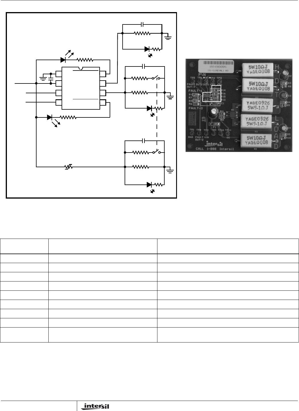
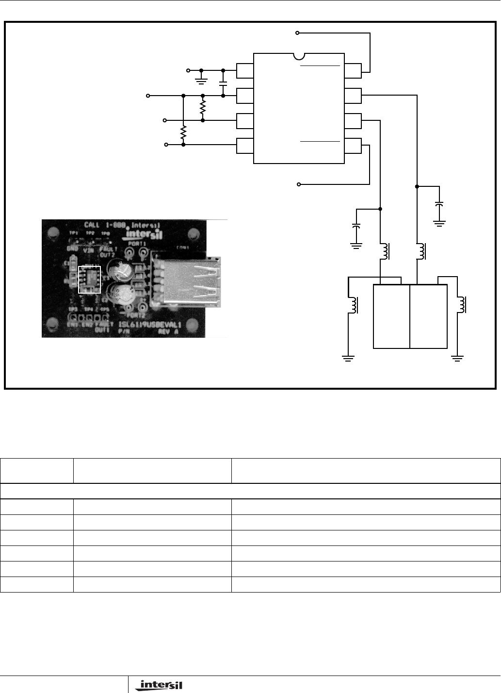
Figure 21 illustrates the RC network needed with suggested
component values and the configuration of the relevant pins
for each autoreset channel.
Description of Operation
Initially as voltage is applied to VIN, the pull up resistor (Rpu)
provides for pull up to VIN on both the ENABLE pin asserting
the output once VIN > 2.5V and on the FLTn pin. Once
turned on and an overcurrent (OC) condition occurs the IC
provides CR protection for 10ms and then the FLTn pin pulls
low through Rpu and also pulling the ENABLE low thus
resetting the device fault condition. At this time the Rpu
charges the cap and the voltage on the ENABLE/FLTn node
rises until the ENABLE > 2.0 and the output is asserted on
once again. This automatic reset cycle will continue until the
OC fault no longer exists on the output. After several
seconds in this mode of operation the IC thermal protection
invokes adjusting the timing of the on-off cycle to prevent
excessive thermal dissipation in the power switch protecting
itself and surrounding circuitry. See Figure 22 for operation
waveform.
.
Applications
•USB
• 2.5V to 5V up to 10W power port protection
FIGURE 21.
VIN
ENABLE
ISL6119H
FLTn
GND
Rpu = 2K
C = 0.1µF
FIGURE 22. AUTO RESET OPERATION
IOUT 0.5A/DIV
VOUT 2V/DIV
VIN/FLTn 5V/DIV
0A
0V
4ms/DIV
ISL6119